FILE VER LAST ISSUE LANG. PAGE
GCM02-MT-ING4 NEW.doc c/02 04/03/2003 ENG Page 37 of 57
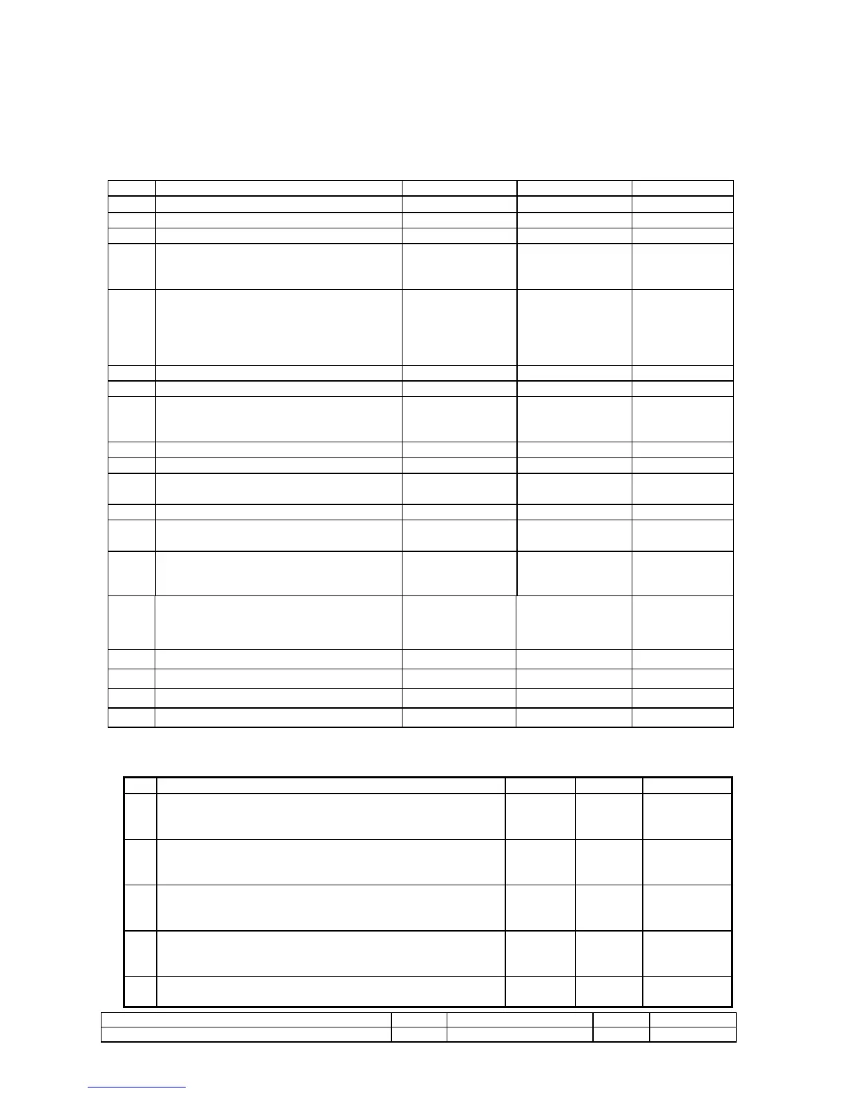
2.12.2 PARAMETERS
The electrical parameters (V-Hz-A-KVA etc) are set in the factory, combining the two modules. The Pressure, Temperature, and Fuel
Level indications depend on the tolerances allowed by the various probes. The temperature reading is particularly closely checked and
calibrated.
When the MP02 module is changed, the electrical measurements may also need to be adjusted.
Changeable measurements:
N° DESCRIPTION VALUE FIELD MODIFICATION
1 Regulation generator voltage 0 - 600V
2 Regulation frequency Hz gen-set 40÷70Hz
3 Regulation current mains and gen-set 0-3000A
4 Regulation zero current
To bring the current to zero and to press “reset” to
confirm the operation
5 Regulation of the CT…../5° 1000 10-15-20-25-40-50-
60-80-100-150-200-
250-300-400-500-
600-800-1000-1200-
1500-2000-3000/5A
6 Regulation power factor (cos f)
7 Regulation transducer oil pressure VDO-MTU-VEGLIA
8 Regulation zero oil pressure
To bring the oil pressure to zero and to press
“reset” to confirm the operation
9 Regulation reading oil pressure
10 Regulation TM transducer VDO-MTU-VEGLIA
11 Regulation zero TM
Not to change
12 Regulation reading TM
13 Regulation transducer fuel level VDO-VEGLIA-
MANUAL
14 Regulation zero LC
To bring the fuel level to zero and to press “reset”
to confirm the operation
15 Regulation reading LC
To bring the fuel level at the most and to press
“reset” to confirm the operation
16 Regulation zero VB
17 Regulation reading VB
18 Regulation current CB
19 Regulation differentials 500/1 500-700-1000/1
2.12.3 TIME SETTINGS
N° DESCRIPTION VALUE FIELD MODIFICATION
1 Number of starting attempts.
This establishes after how many starting attempts the failed starting
function is to be enabled.
4 2 - 10
2 Starting time and pause
This establishes the starting time and the pause between one starting
attempt and another.
5” 3 – 15”
3 Mains enabling delay
When the mains returns within the established limits following the set
time, the output is switched from generator to mains.
60” 5 - 255”
4 Generator enabling delay
The load output is enabled following a set time that is triggered by the
motor started signal (minimum 5 secs.)
5 3 - 255”
5 Starting delay
This makes the GE insensitive to micro-disconnections due to a pre-