1.4 FUNCTIONAL DESCRIPTION OF THE CONTROL PANEL COMPONENT
Description of the components.
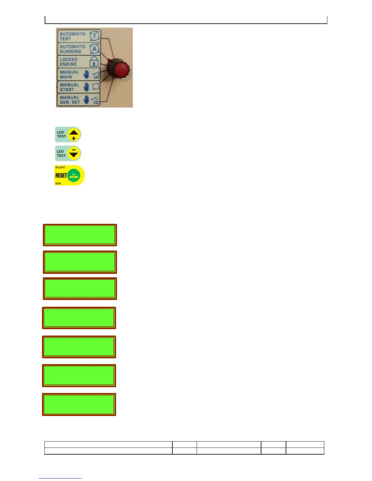
Programming switch.
Type of operational mode selection
1. Automatic test (T)
2. Standard automatic run mode (A)
3. Locked status – electronics disabled, used for
maintenance.
4. Utility power supply forced from mains (CR).
5. Enable start push button to start in manual mode.
6. Utility power supply forced from generator (CG).
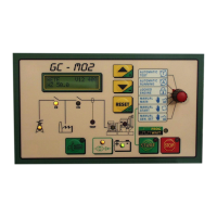
Display reading selection push buttons.
These are used to select the reading page required and to program the weekly timer.
DIFFERENTIAL TEST, with the switch in BLOCK, to operate for 2” the buttons+/- “TEST
LED” and while the led are turned on, to press RESET to have the differential protection.
Reset/Enter push button used to reset the functions and to eliminate an alarm status
(RESET)and also to confirm parameters entered in the programming phase (ENTER)
To push one time to exclude the acoustic alarm (SILENT) and to fix the signalling of
alarm, two times to reset.
DESCRIPTION OF THE VARIOUS READING PAGES
When the mains are connected these readings are automatically displayed
that indicate the mains voltage and frequency. The current on the phase 1
is displayed if the CT are connected and reseted on the load.
The three line voltages between one phase and another are displayed for
the detailed control of the mains…
It indicates the three star voltages between phase and neutral
The three currents of phase enable to verify the situation about the load on
the single phase of the mains. This page is displayed if the CT are
connected and reseted on the load.
The powers indicate the state and the load type on the mains:
KVA=kilovoltampere=apparent power; KW=kilowatt=real power;
KVAr=kilovar=reactive power. This page is displayed if the CT are
connected and reseted on the load.
Cosfì= power factor = phase displacement angle between voltage and
current, with the normal load it indicates L 0,xx, if with capacitive load it
indicates C 0,xx. This page is displayed if the CT are connected and
reseted on the load
When the gen-set is running the gen-set voltage, the frequency and the
current on the phase 1 are displayed.