FUEL LEVEL
%
2.6.5. FUEL LEVEL(15)
The measure is foreseen for the level transducers Veglia or VDO from 0 to 200 Ohm,
for different values it needs the manual setting, the scale is in % from 0 to 110% max .
PROGRAMMING
From the menu various setting, to select for the analogic input 15, the kind of
transducer Veglia or VDO.
ADJUSTMENT PROGRAMMING TO ANY TYPE OF FLOAT
The programming of the measure of the fuel level is effected with the float outside of
the tank.
To activate the switch 4 to enter in the programming menu.
To go to page “REG. ZERO LC” (in the pages REGOLAT. MEASURES).
To put the measuring stick in the position of void. Press ENTER.
To go to page “REG. LETT. LC” To put the measuring stick in the position of full. Press
ENTER.
The unit will calculate automatically the run of the float aligning the reading.
Turn back the switch 4 on OFF.
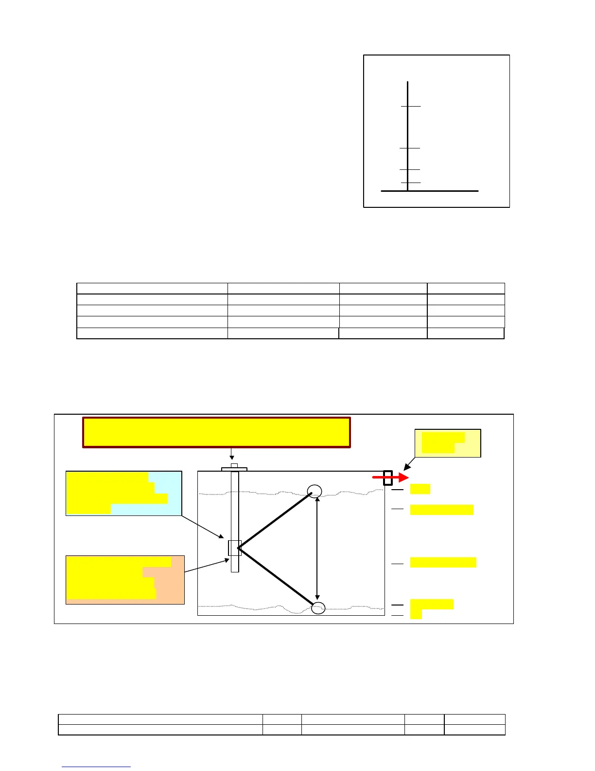
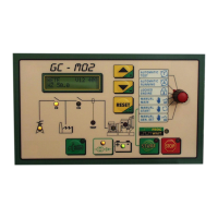
2.6.6 FUEL PUMP COMMAND
The GC-M02 control panel is pre-arranged to command the fuel pump that fills the daily tank. The fuel level probe, (VDO) that
commands the digital tester that indicates the percentage of fuel inside the tank, electronically establishes the following levels:
DESCRIPTION INDICATION FUNCTIONS LEVEL %
Pump stoppage Pump LED OFF Pump OFF 80%
Pump starting Pump LED ON Pump start 40%
Fuel reserve Display Buzzer (DEFAULT) 10%
Lack fuel Display Delayed alarm and stop 5%
The tripping thresholds can be programmed.
The failed installation of the level probe or the circuit breakage automatically excludes the operation of the pump and display indication.
When the level probe is being installed the real upward and downward excursion of the level rod must be taken into account.