PAGINA
GCM02-MT-ING4 NEW.doc c/02 04/03/2003 ITA Page 2 of 57
INDEX
AUTOMATIC MICROPROCESSOR CONTROL PANEL FOR
STAND-BY GENERATOR.........................................................................................................................1
INDEX......................................................................................................................2
1. USER MANUAL.........................................................................5
NTRODUCTION...........................................................................................................5
We congratulate you for having purchased the GC-M02 control panel for handling your generator unit. As you
read through this manual you will realise the outstanding performance and variety of applications offered by
this supremely technological unit............................................................................................5
This electronic microprocessor module not only completely controls the generator and its switching but is also
pre-arranged for the direct serial communication with a PC or, using a GSM unit your generator can be
completely remote controlled from miles away............................................................................5
The GC-M02 unit is equipped with a complete set of digital testers that are required to monitor all mains,
generator and motor parameters............................................................................................5
To make the control of the unit absolutely comprehensible the manual is split up into two parts, namely:..........5
1.1 PURPOSE..............................................................................................................................................................................5
1.2 OPERATIONAL PRINCIPLE...........................................................................................................................................6
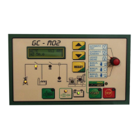
1.3 VIEW OF THE GC-M02 UNIT................................................................................................................................................7
1.4 FUNCTIONAL DESCRIPTION OF THE CONTROL PANEL COMPONENT.......................................................................7
1.4 FUNCTIONAL DESCRIPTION OF THE CONTROL PANEL COMPONENT.......................................................................8
1.5. COMMANDS AND OPERATIONAL MODES.....................................................................................................................11
1.6 PROGRAMMING..................................................................................................................................................................12
1.7. VARIOUS CONTROLS.......................................................................................................................................................12
LED TEST.......................................................................................................................................................................12
ALARM SILENCING.......................................................................................................................................................12
1.8. SPECIAL FUNCTIONS.......................................................................................................................................................12
1.9 SIMPLE MAINTENANCE WORK..................................................................................................................................13
2. TECHNICAL MANUAL..................................................................................................14
2.1 CONSTRUCTIONAL DESCRIPTION OF THE CONTROL PANEL .............................................................................14
2.2. OPERATION........................................................................................................................................................................15
2.3 DETAILED DESCRIPTION OF HOW THE CONTROL UNIT WORKS...............................................................................15
2.4 MANUALLY CONTROLLED FUNCTIONS..........................................................................................................................17
2.4.1 POWER SUPPLY FROM MAINS (manual command)........................................................................................17
2.4.2 MANUAL STARTING............................................................................................................................................17
2.4.3 POWER SUPPLY FROM GENERATOR.............................................................................................................17
2.4.4 MANUAL STOPPAGE...........................................................................................................................................17
2.5 VARIOUS FUNCTIONS AND UTILITIES......................................................................................................................18
2.5.1 CC12 AND 24V POWER SUPPLY CIRCUITS....................................................................................................18
2.5.2 COMMAND RELAYS ............................................................................................................................................18
2.5.3 MOTOR STARTED READING..............................................................................................................................18
2.5.4. MOTOR PRE-HEATING......................................................................................................................................18
2.5.5 AUTOMATIC BATTERY CHARGER ....................................................................................................................19
2.6 MOTOR AND ALARM PARAMETER READING................................................................................................................20
2.6.1 POSITIVE MOTOR PROTECTION INPUTS........................................................................................................20
2.6.2 ANALOGUE MOTOR PARAMETER READING INPUTS (PRESSURE, TEMPERATURE AND FUEL LEVEL)20
2.6.3. OIL PRESSURE...................................................................................................................................................21
2.6.4. MOTOR TEMPERATURE....................................................................................................................................21
2.6.5. FUEL LEVEL(15)..................................................................................................................................................22
PROGRAMMING............................................................................................................................................................22
2.6.6 FUEL PUMP COMMAND......................................................................................................................................22