FILE VER LAST ISSUE LANG. PAGE
GCM02-MT-ING4 NEW.doc c/02 04/03/2003 ENG Page 25 of 57
33 34 35 36
0,1Ω
5W
3 x CT 100-2000/5A
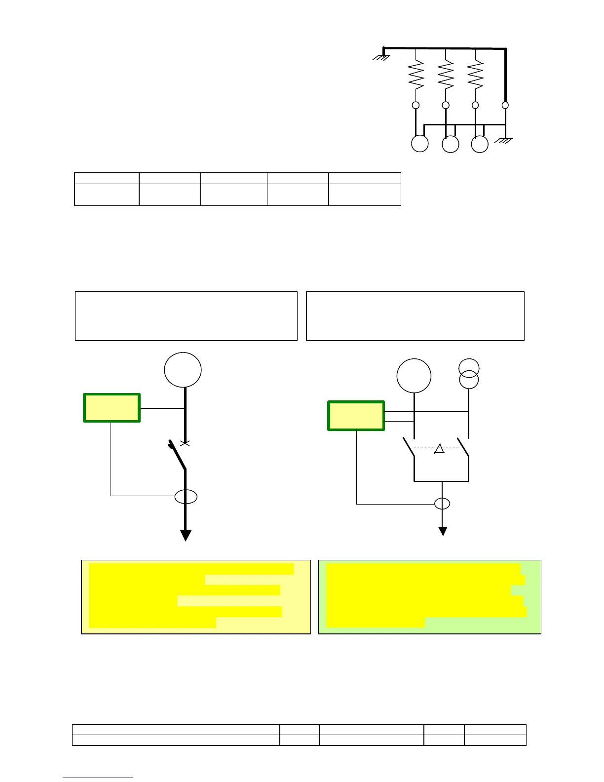
CURRENT MEASUREMENTS
The three current measurements for CT …/5A are 0,5 class up to 1000 A and 1
class from 1000 to 2000 A. The ammeter circuits are made up of three 0,1Ω 5W
resistances, with a dissipation of 2,5W at maximum current (5 A). They can work at
a constant overload of 20% 6 A, and have a short-circuit protection of 15 A for 3” or
20 A for 2”.
To ensure protection against overloading and short-circuits the CTs used must
have a minimum power of => 4VA. Where the CTs also power other equipment,
this power is increased to suit the power these require plus losses in the wires.
Consumption table in VA per metre of wire.
SECTION mm2 1,5 2,5 4 6
VA
0,685 VA 0,41 VA 0,254 VA 0,169 VA
CONNECTIONS CT
CT PHASE R-L1 33 – 36 CT PHASE S-L2 34 – 36 CT PHASE T-L3 35 – 36
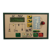
The M02 is provided for managing generator units that operate automatically or manually, with or without mains power supply/generator
switching over. The circuit in which the CTs are installed and the readings shown on the display vary depending on their application. For
example:
The type of operation is selected on the basis of the positioning of the current transformers (CT), via “misc. settings” by selecting:
1. for units without switching (CT ON GENERATOR );
2. for units with switching (CT ON SWITCHING ).
All the generator’s electrical readings are displayed, Volt, Hz,
Amp, Kw, Kva, Kvar, Power factor.
When the mains power supply is connected voltages and
frequencies are displayed.
The generator’s electronic trip switch is active to protect it
against overloading and short-circuits.
All the generator’s electrical readings are shown, Volt, Hz,
Amp, Kw, Kva, Kvar, Power factor. The same readings are
carried out on the power supply when the Mains power
supply connector (conn 25) is closed. This Connector also
activates the electronic cut-out for overloading on the mains
power supply contactor (CR).
Isolated generator without mains power supply generator
switching, or with separate switching.
The CTs only read the generator current.
Emergency generator backing up the mains power
supply, with mains power supply generator switching.
The CTs read the mains power supply and generator