Afinia H800+ 3D Printer User’s Manual
38
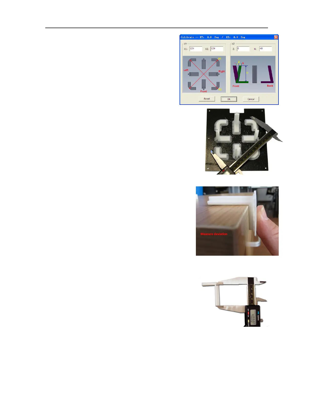
Open Calibrate from the 3D Print menu. Measure the
X1 and X2 length, as shown in the pictures below.
IMPORTANT NOTE: Before you enter any new
calibration values, the bar at the very top of the screen
should read: XY: 0.00 deg / XZ: 0.00 deg. If not, click the
Reset button!
Measure the calibration print from front left to rear right corners of
the printed parts on the platform for the X1 measurement, and the
rear left to front right for the X2 measurement.
Do not include the raft or support material when taking these
measurements!
Enter the X1 and X2 measurements into the labeled boxes.
Next, carefully remove the Front Center ‘L’ shaped component
from the platform and check the inside angle. If it is not 90º,
measure the exact distance in millimeters that the end of the
long arm of the part needs to move to get the angle to be 90º;
enter that distance into the Z box.
If the angle is less than 90º, the value to be put into the Z box
will be positive. If the angle is more than 90º, the value will be
negative. For example, if the end of the long arm is 1.3 mm
above the surface, enter -1.3 in the Z box.
Finally, measure the long arm of the Front Center component from
the inside of the angle to the end, which should be 40mm. Enter
the exact measured value into the H box of the Calibrate dialog box.
Click OK to record all these values and exit the calibration.
Checking the X1 Measurement