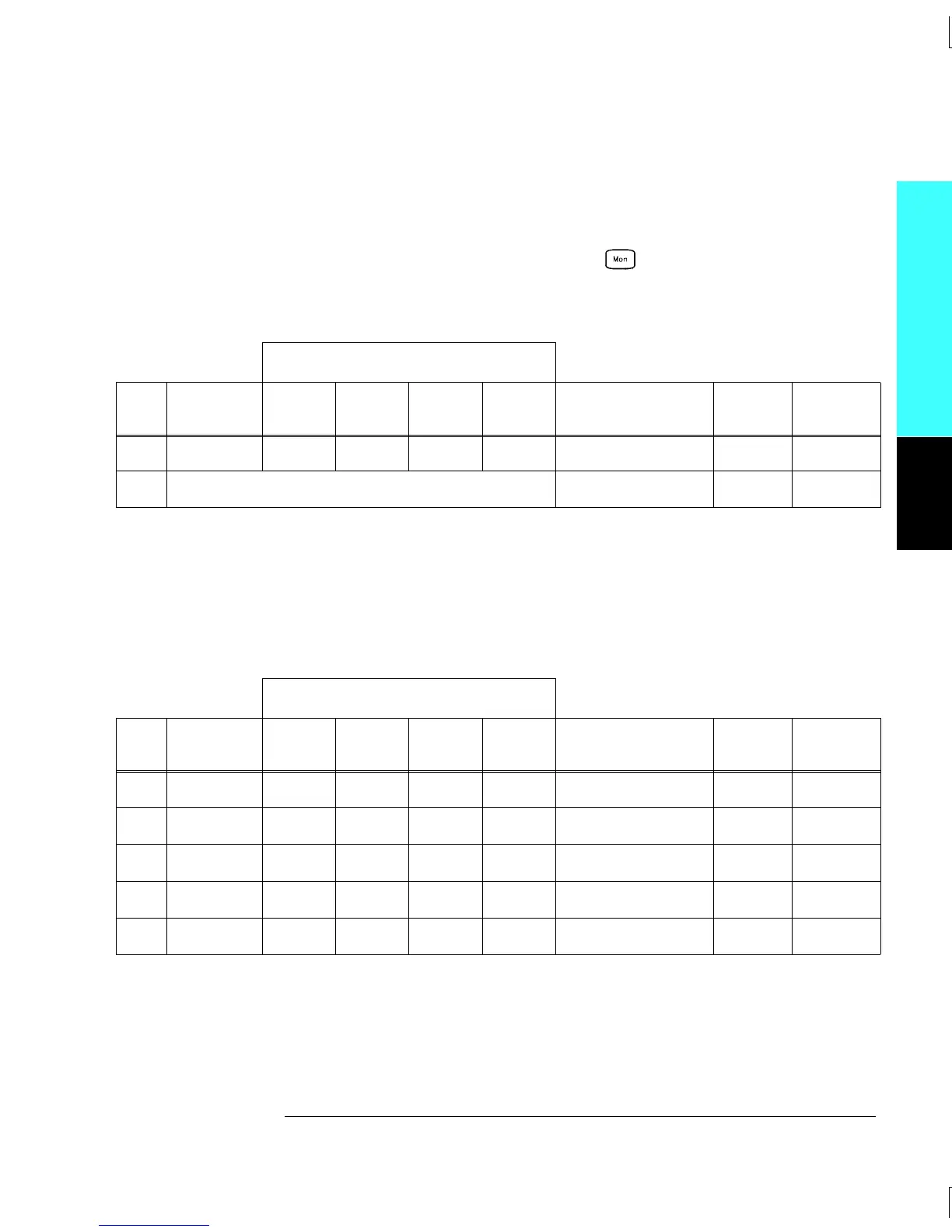
Tests 9 - 10: Open all channels on the module by performing a Factory Reset.
Configure Channel 08 (module in slot 200) as follows: 4-wire ohms,
1 kΩ range, and 5
1
⁄
2
digits.
Enable reading monitoring by pressing on the selected channel
(or use the ROUTe:MON command). Record the 4-wire ohms
measurements from the external DMM in the following table.
External DMM Ohmmeter Connections
Test
#
Channel
Configured
HI LO
HI
Sense
LO
Sense
Measured Value
Test
Limit
Relay
Measured
9 Ch 08 P3 P3 P2 P2 __________ Ohms — —
10 Subtract (Test 9 – Test 4) __________ Ohms
2.00Ω
K328
Tests 11 - 27: Open all channels on the module by performing a Factory Reset.
For each test, close only the channels shown in the “Channels Closed”
column below (module in slot 200). Turn the Monitor Mode “off” and
select “Banks Joined” from the Advanced menu. Record the 4-wire
ohms measurements from the external DMM in the following table.
External DMM Ohmmeter Connections
Test
#
Channels
Closed*
HI LO
HI
Sense
LO
Sense
Measured Value
Test
Limit
Relay
Measured
11 Ch 16 & 1 P3 P3 P1 P1 __________ Ohms
2.00Ω
K301
12 Ch 16 & 2 P3 P3 P1 P1 __________ Ohms
2.00Ω
K302
13 Ch 16 & 3 P3 P3 P1 P1 __________ Ohms
2.00Ω
K303
14 Ch 16 & 4 P3 P3 P1 P1 __________ Ohms
2.00Ω
K304
15 Ch 16 & 5 P3 P3 P1 P1 __________ Ohms
2.00Ω
K305
* Only the channels currently under test should be closed at one time. All other channels should be open.
Continued on next page...
Module Reference
4
Chapter 4 Calibration Procedures
Relay Verification
99

 Loading...

