4263B
T
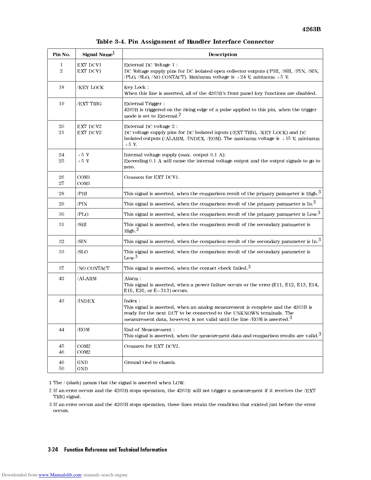
able 3-4.
Pin Assignment
of
Handler
Interface
Connector
Pin
No
.
Signal
Name
1
Description
1
2
EXT DCV1
EXT
DCV1
External DC
Voltage
1:
DC
Voltage
supply
pins
for
DC
isolated
open
collector
outputs
(/PHI,
/SHI,
/PIN,
/SIN,
/PLO
,
/SLO
,/NO
CONTA
CT). Maximum
voltage is
+24 V
, minimum
+5 V
.
18 /KEY
LOCK
Key
Lock
:
When
this
line
is
asserted,
all
of
the
4263B
's front
panel key
functions are
disabled.
19 /EXT
TRIG
External
Trigger
:
4263B
is
triggered
on
the
rising
edge
of a
pulse applied
to this
pin, when
the
trigger
mode
is
set
to
External.
2
20
21
EXT
DCV2
EXT
DCV2
External
DC
voltage
2
:
DC
voltage
supply
pins
for
DC
Isolated
inputs
(/EXT TRIG,
/KEY LOCK)
and DC
Isolated
outputs (/ALARM,
/INDEX, /EOM).
The maximum
voltage
is
+15
V
,
minimum
+5
V
.
24
25
+5
V
+5
V
Internal
voltage supply
(max. output
0.1
A):
Exceeding
0.1
A
will
cause
the
internal
voltage
output
and
the
output
signals
to
go
to
zero
.
26
27
COM1
COM1
Common
for
EXT
DCV1.
28 /PHI This
signal
is asserted,
when the
comparison result
of the
primary
parameter
is
High.
3
29 /PIN This
signal
is
asserted,
when
the
comparison
result
of
the
primary
parameter
is
In.
3
30 /PLO This
signal
is
asserted,
when
the
comparison
result
of
the
primary
parameter
is
Low
.
3
31 /SHI This
signal
is
asserted,
when
the
comparison
result
of
the
secondary parameter
is
High.
3
32 /SIN This
signal
is
asserted,
when
the
comparison result
of
the
secondary
parameter
is
In.
3
33 /SLO This signal
is
asserted,
when
the
comparison
result
of
the
secondary
parameter
is
Low
.
3
37 /NO
CONT
A
CT
This
signal
is
asserted,
when
the
contact
check
failed.
3
42 /ALARM Alarm
:
This
signal
is
asserted,
when
a
power
failure
occurs
or
the
error
(
E11
,
E12
,
E13
,
E14
,
E15
,
E20
,
or
E
0
313
)
occurs
.
43 /INDEX Index
:
This signal
is asserted,
when an
analog
measurement
is
complete
and
the
4263B
is
ready
for the
next DUT
to be
connected to
the
UNKNOWN
terminals
.
The
measurement
data, however
,is
not valid
until
the
line
/EOM
is
asserted.
3
44 /EOM End of Measurement :
This signal is asserted, when the measurement data and comparison results are valid.
3
45
46
COM2
COM2
Common for EXT DCV2.
49
50
GND
GND
Ground tied to chassis
.
1
The / (slash) means that the signal is asserted when LOW
.
2
If an error occurs and the 4263B stops operation, the 4263B will not trigger a measurement if it receives the /EXT
TRIG signal.
3
If an error occurs and the 4263B stops operation, these lines retain the condition that existed just before the error
occurs.
3-24 Function Reference and Technical Information