4263B
The
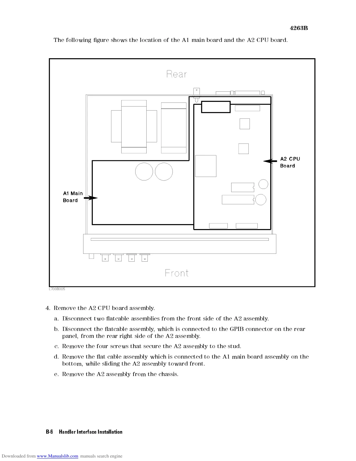
following gure
shows the
location
of
the
A1
main
board
and
the
A2
CPU
board.
4.
Remove the
A2
CPU
board
assembly
.
a.
Disconnect two atcable assemblies from the front side of the A2 assembly
.
b. Disconnect the
atcable assembly
, which is connected to the GPIB connector on the rear
panel, from the
rear right side of the A2 assembly
.
c. Remove the four screws that secure the A2 assembly to the stud.
d. Remove the at cable assembly which is connected to the A1 main board assembly
on the
bottom, while sliding the A2 assembly toward front.
e. Remove the A2 assembly from the chassis.
B-6 Handler Interface Installation