Chapter 5: Troubleshooting
Power Supply Trouble Isolation
5–23
7KHVHWURXEOHLVRODWLRQLQVWUXFWLRQVKHOSLVRODWHWKHSUREOHPWRWKHDVVHPEO\OHYHOZKHQWKH
SRZHUVXSSO\LVQRWRSHUDWLQJ%HFDXVHRIDGYDQFHGSRZHUVXSSO\SURWHFWLRQIHDWXUHVWKH
SUREOHPPD\QRWEHZLWKWKHVXSSO\LWVHOIDQGWKHUHIRUH\RXZLOOQHHGWRZRUNWKURXJKWKH
SURFHGXUHV\VWHPDWLFDOO\WRGHWHUPLQHWKHVRXUFHRIWKHIDXOW
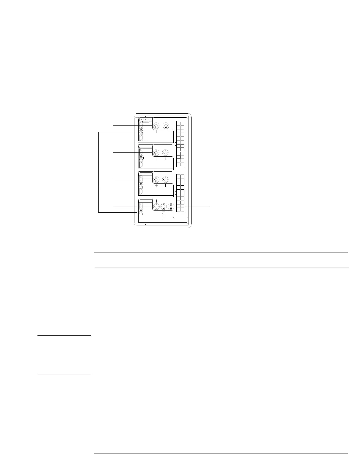
1 Check the power supply voltages on the power supply. See Figure 5-6 for the location
of these test points. Table 5-1 shows the allowable range of power supply voltages.
Figure 5-6
Power Supply Voltage Test Locations
Table 5-1 Power Supply Voltage Limits
Power supply adjustment procedure
WARNING SHOCK HAZARD!
The maintenance described in this section is performed with power supplied to the oscilloscope
and with the protective covers removed. Only trained service personnel who are aware of the
hazards involved should perform the maintenance Read the safety summary at the back of this
book before proceeding. Failure to observe safety precautions may result in electric shock.
2
Use a volt meter to monitor each of the supply’s output voltages. Use a long
screwdriver, being careful not to touch any other components, to turn the adjustment
screw for each supply voltage until it is within the specified limits.
Supply Voltage Specification Limits
+5.1 V ± 0.4% +5.08 V to +5.12 V
+3.3 V ± 0.4% +3.33 V to +3.36 V
+12.25 V ± 0.4% +12.2 V to +12.3 V
-12.25 V ± 10%V -11.03 V to -13.48 V
+3.3 V
+3.3 V
+5.1 V
+12.25 V
-12.25 V
Module adjustment screws