Installation 1
Installation and First Startup 33
3
Remove the GC pneumatics cover. (You may need to
disconnect any vent lines.)
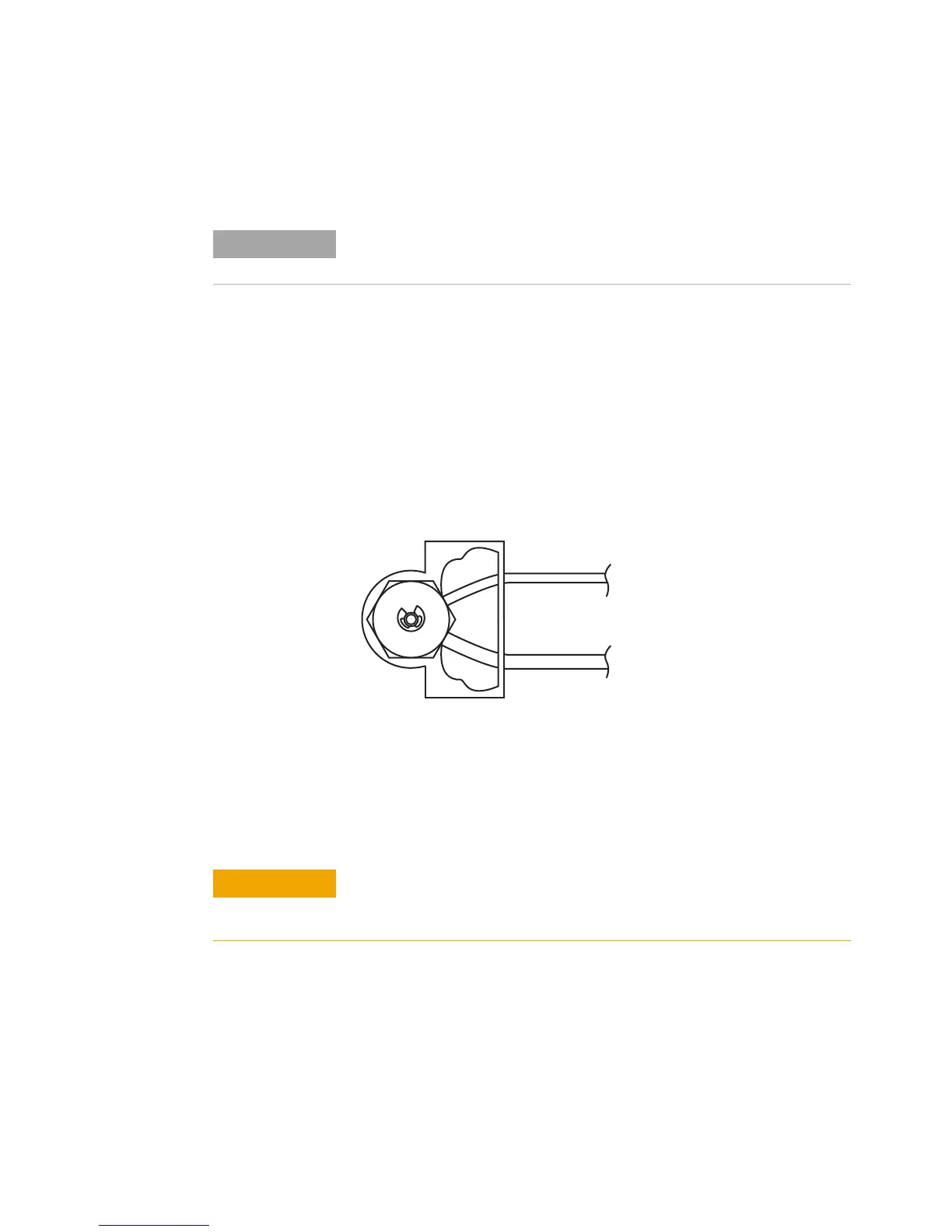
4 Splice into the inlet carrier gas tubing.
a Locate the inlet carrier gas line. The inlet carrier gas
line is a 1/16- inch stainless steel tube that runs from
the inlet EPC module to the inlet, usually beside the
inlet carrier cover on the oven top. For split/splitless
and multimode inlets, there is also a stainless steel
septum purge vent line. The septum purge vent line is
larger in diameter, and runs to the septum purge vent
on the EPC module.
b Using the precision tubing cutter, cut the carrier gas
line leading into the inlet at approximately 3 to 5 cm
from the septum head.
If you purchased the G3521A 7890A S/SL MMI Weldment for Headspace, install it
now. Skip step 4.
Carrier gas line is 1/16-inch id.
It is always slightly smaller than
the septum purge line.
Septum purge gas line is slightly
larger than the carrier gas line.
7890A Multimode inlet shown. Other inlets similar.
Cut the tubing as square as possible. Be careful to avoid kinks in the
tubing. Avoid deforming the tubing. The cut should not be beveled or
angled.

 Loading...


