28
Introducing the Agilent 81101A Pulse Generator
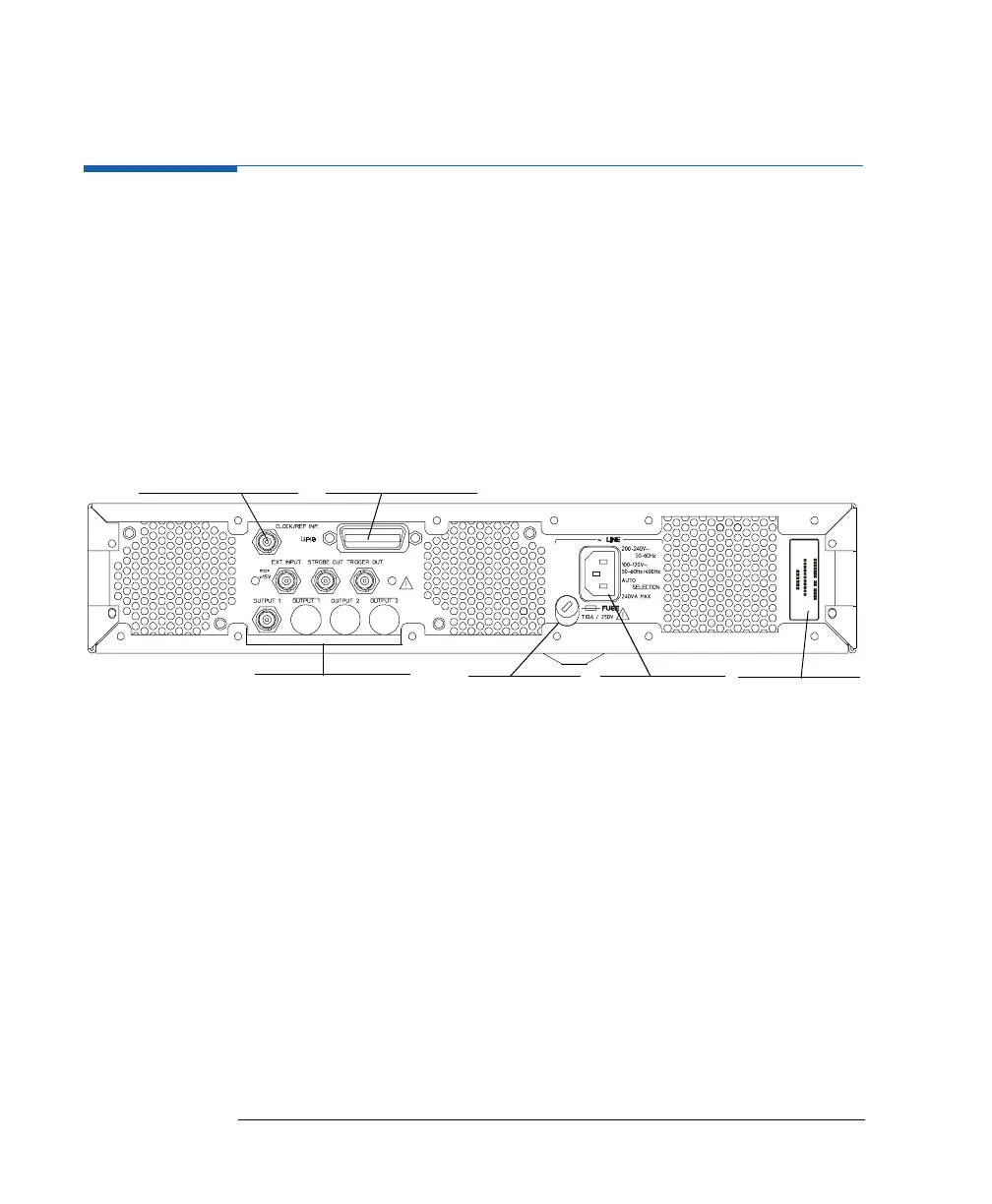
The Rear Panel
The Rear Panel
The rear panel always provides two connectors:
The input connector for external frequency reference (CLOCK/REF
INP.). This input can be used if a higher frequency accuracy is
required, or if you need frequency locking.
The GP-IB connector providing the interface for remote control.
The following figure shows the rear panel view with the option UN2.
With option UN2 the major inputs and outputs of the instrument (as
described in The Front Panel on page 18) are available at the rear
panel:
external input (EXT INPUT)
strobe output (STROBE OUT)
trigger signal (TRIGGER OUT)
signal output (OUTPUT)
Inputs and Outputs
Fuse Holder AC Line Socket
Serial Number
GP-IB ConnectorExternal Reference