57
Using the Agilent 81101A
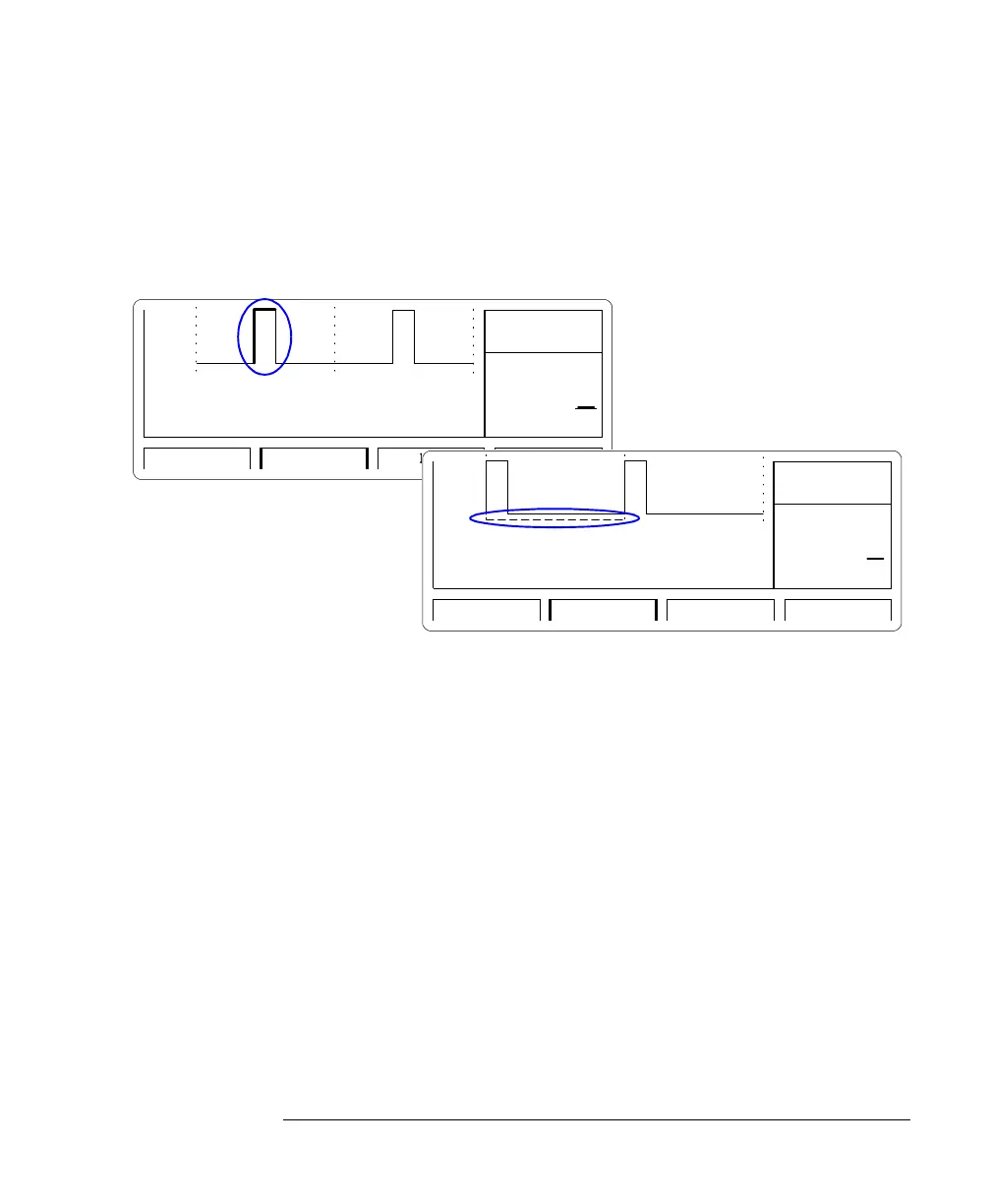
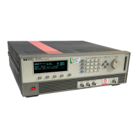
The Output Screen
When you press SHIFT + MORE (GRAPH) while one of the timing parameters is
selected, you will see a graphical representation of the timing
parameters. The currently selected parameter is displayed in the Modify/
Enter area and is indicated by dashed or bold lines in the graphical
display.
Use the left/right cursor keys to toggle between the individual timing
parameters.
NOTE
Note that in graphics mode you can only adjust the values of each
parameter, not the parameter format. If you want to change the format of
a parameter, for example W
IDTH
to D
TY
C
YC
, you must be in text mode to
select the parameter name with the cursor.
Pulse Period Parameter
Set the pulse period as either P
ERIOD
or F
REQUENCY
.
If you select the CLK-IN as the pulse period source on the Mode/Trigger
screen, the pulse period/frequency is determined from the signal applied
to the CLOCK/REF INP. connector:
M
EAS
O
NCE
The external signal is measured only once. Press ENTER to measure
again.
ns
100.0
OUTPUT TRG-LEVLIMITSMODE/TRG
1
OFF
Width1
µ
µµ
µ
s
1.000
OUTPUT TRG-LEVLIMITSMODE/TRG
1
OFF
PERIOD