3-10
Front/Rear Panel
Rear Panel Features and Connectors
Rear Panel Features and Connectors
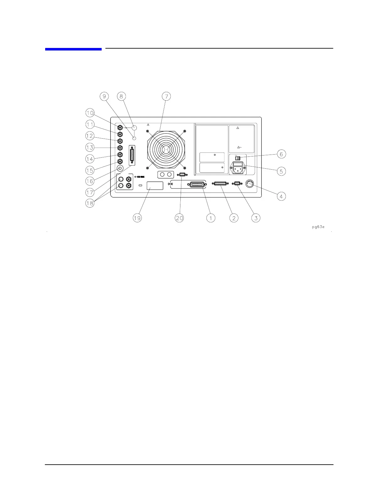
Figure 3-4 8753ET/ES Rear Panel
Figure 3-4 illustrates the features and connectors of the rear panel, described below.
Requirements for input signals to the rear panel connectors are provided in the
specifications and characteristics chapter.
1. GPIB connector. This allows you to connect the analyzer to an external
controller, compatible peripherals, and other instruments for an
automated system. Refer to Chapter 7 , “Options and Accessories,” for
GPIB information, limitations, and configurations.
2. PARALLEL interface. This connector allows the analyzer to output to a
peripheral with a parallel input. Also included, is a general purpose
input/output (GPIO) bus that can control eight output bits and read five
input bits through test sequencing. Refer to Chapter 7 , “Options and
Accessories,” for information on configuring a peripheral. Also refer to
“The GPIO Mode” in the “Operating Concepts” chapter of the user’s guide.
3. RS-232 interface. This connector allows the analyzer to output to a
peripheral with an RS-232 (serial) input.
4. KEYBOARD input (mini-DIN). This connector allows you to connect an
external keyboard. This provides a more convenient means to enter a title
for storage files, as well as substitute for the analyzer's front panel
keyboard.
5. Power cord receptacle, with fuse. For information on replacing the
fuse, refer to the installation and quick start guide.
6. Line voltage selector switch. For more information, refer to the
installation and quick start guide.

 Loading...


