1-13
Troubleshooting the Analyzer
To perform initial verification
6 Step 6. Check signals required for power up.
a Remove the top cover.
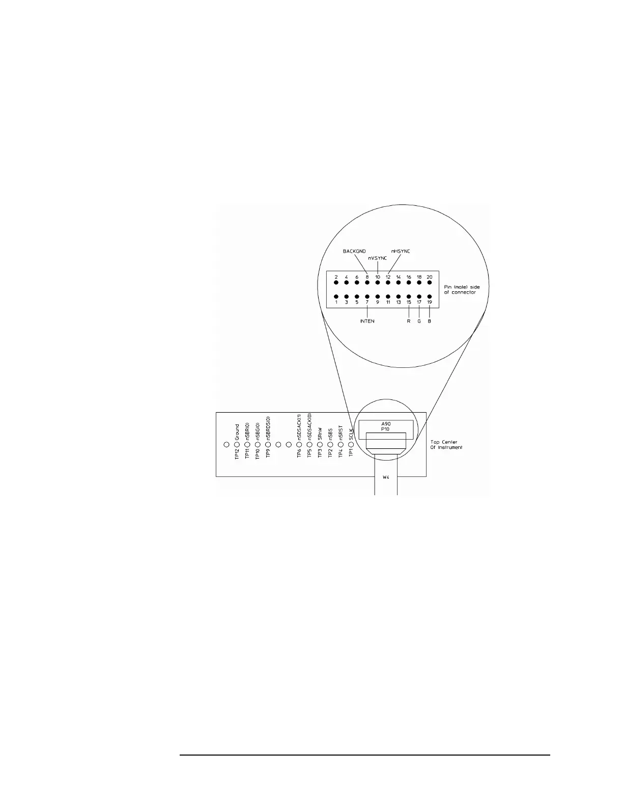
b Connect a logic probe to A90 TP4 and its ground clip to A90 TP12.
c Set the power switch off (
O ) then on ( l ) and check that A90 TP4
is a TTL high 10 seconds after power up.
d If TP4 remains low, the A40 CPU assembly is probably faulty.
Before replacing the assembly, go to page 1-15 ‘’To troubleshoot
the power supply,’’ and do Step 7 to check power supply voltages.
e Set the power switch to off
( O ) and disconnect the ribbon cable
from A90 P10.
f Set the power switch to on ( l ).

 Loading...


