1-14
Troubleshooting the Analyzer
To perform initial verification
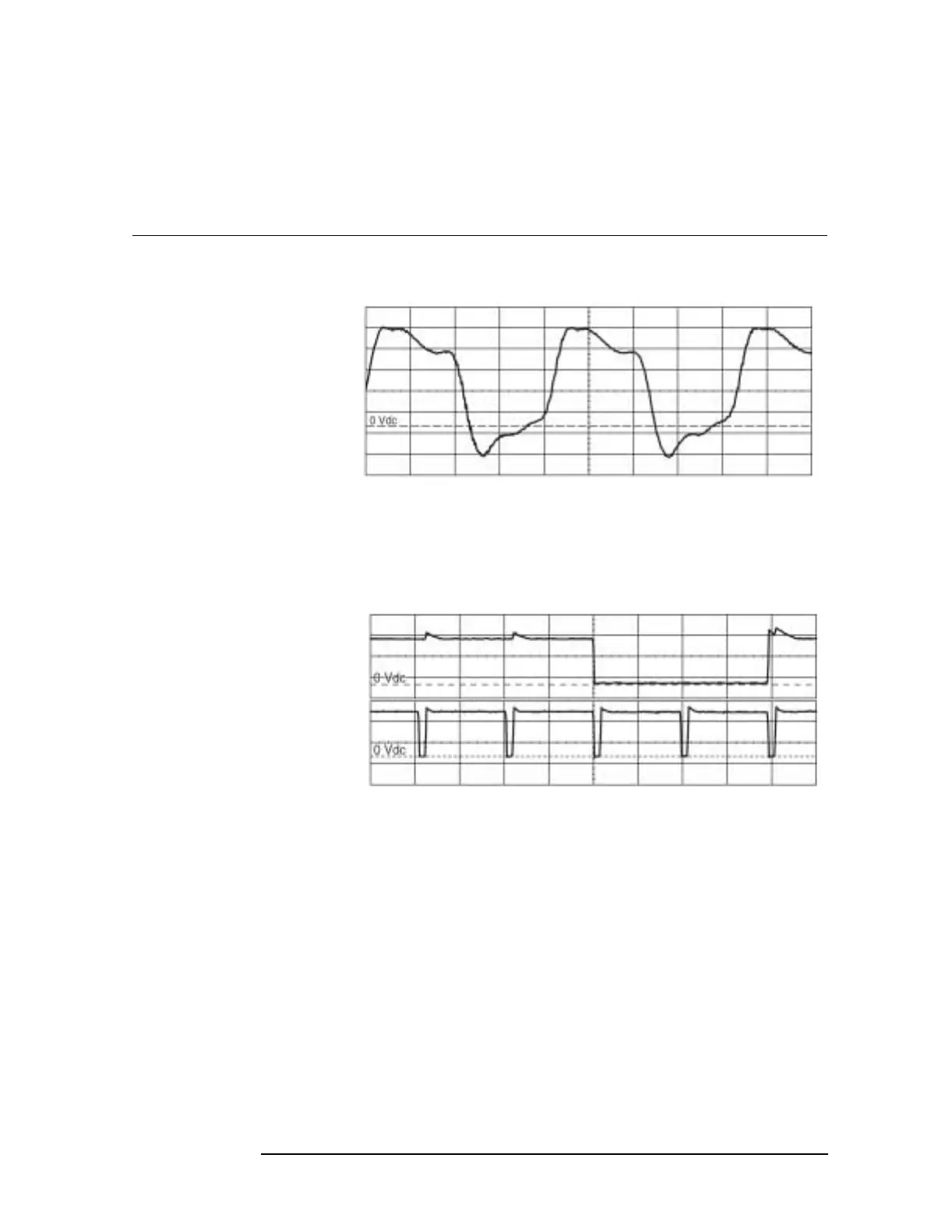
g Using an oscilloscope and 1 MΩ 10:1 probes, check the following
system clock signals.
h If SCLK is incorrect, the A40 CPU assembly is probably faulty.
Before replacing the assembly, go to page 1-15, ‘’To troubleshoot
the power supply,’’ and do Step 7 to check power supply voltages.
i If nVSYNC or nHSYNC is incorrect, the A47 DSP/Display
Controller assembly is probably faulty.
j If the signals are correct, go to page 1-36 ‘’To troubleshoot
power-up failures.’’
Oscilloscope Setup Parameters Waveform
Connect CH1 to A90 TP1 Time
Duty Cycle
CH1 V/div
Input Impedance
CH1 Coupling
Probe Atten
Display Mode
Averaging
Time/div
Tri gger
Trig Src
1V/div
1MΩ
dc
10
Repetitive
8
10 ns/div
Trg’d Sweep
Chan1
SCLK
Connect CH1 to A90 P10 pin 10
Connect CH2 to A90 P10 pin 12
Time
Duty Cycle
Time Relationship
CH1 V/div
Input Impedance
CH1 Coupling
Probe Atten
CH2 V/div
Input Impedance
CH2 Coupling
Probe Atten
Display Mode
Averaging
Time/div
Tri gger
Trig Src
2V/div
1MΩ
dc
10
2V/div
1MΩ
dc
10
Repetitive
8
20 µs/div
Trg’d Sweep
Chan1
nVSYNC and nHSYNC

 Loading...


