1-18
Troubleshooting the Analyzer
To troubleshoot the power supply
3 Check the A96 Primary Power Supply assembly’s ac bias voltages.
a Place the analyzer on the side closest to the keypad.
b Remove the bottom cover.
c Wait five minutes to allow time for the power supply capacitors to
discharge.
d Remove the black power supply shield.
e Connect the power cord and set the power switch to on ( l ).
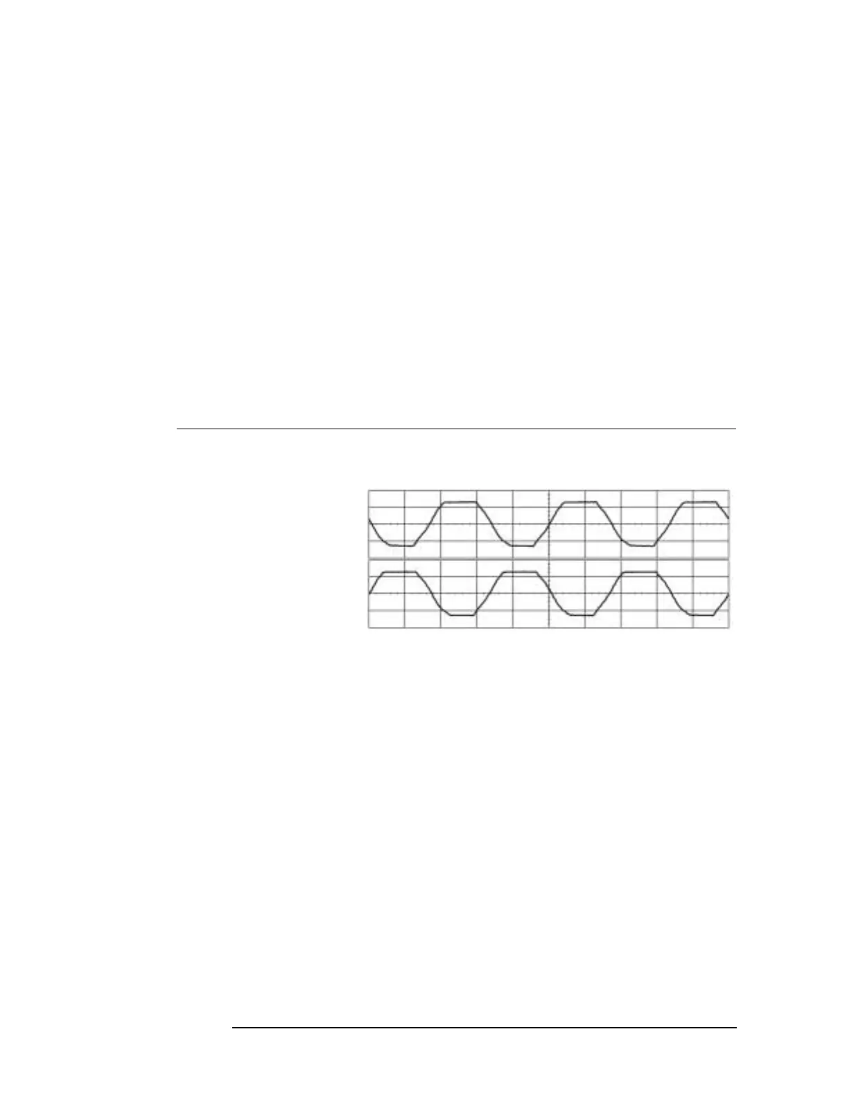
f Using an oscilloscope and two 1
MΩ 10:1 probes, check the
following ac bias supplies. See page 1-19 for component location.
g If the waveforms are incorrect, the A96 Primary Power Supply
assembly is probably faulty.
Oscilloscope Setup Parameters Waveform
Connect CH1 to A95 P352, pin 1
Connect CH2 to A95 P352, pin 4
Pulse Shape
Time Relationship
CH1 V/div
Input Impedance
CH1 Coupling
Probe Atten
CH2 V/div
Input Impedance
CH2 Coupling
Probe Atten
Display Mode
Averaging
Time/div
Trigger
Trigger Level
Trig Src
20 V/div
1MΩ
dc
10
20 V/div
1MΩ
dc
10
Repetitive
8
5 ms/div
Trg’d
Sweep
−1.8 V
Chan1
AC BIAS

 Loading...

