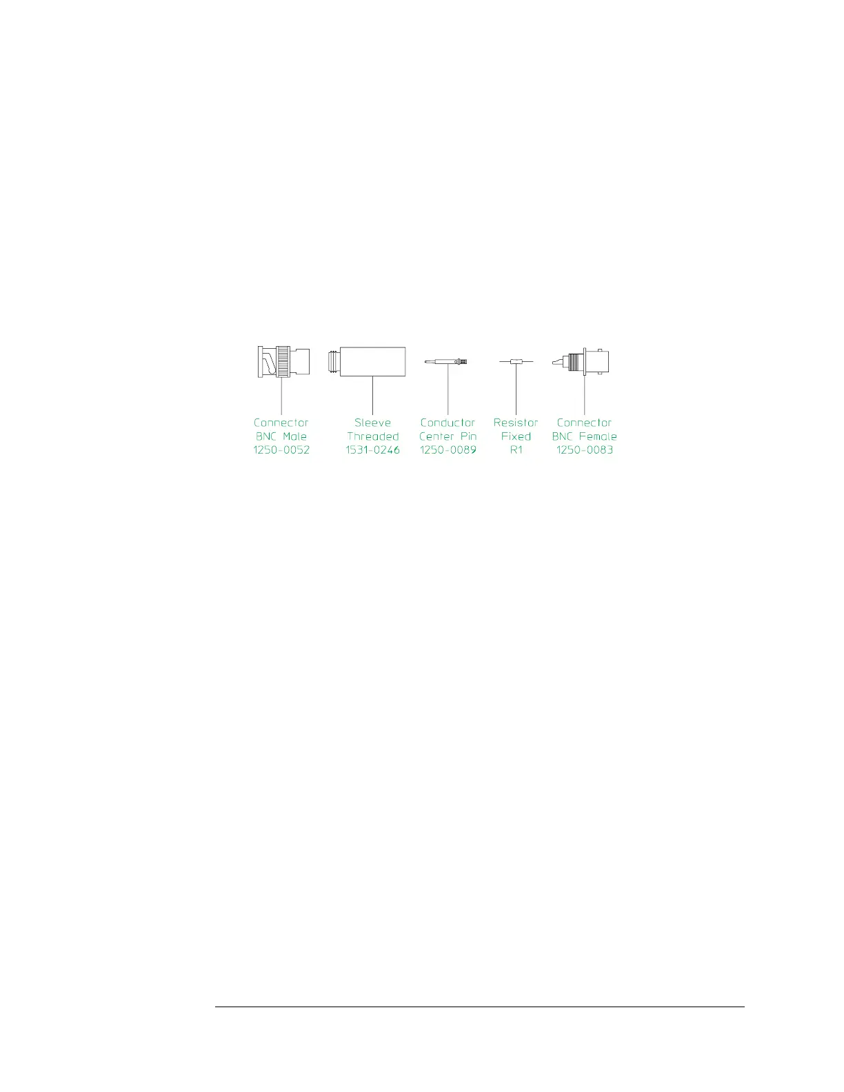
Suggested Assembly for Series Resistor
The following is a suggested assembly for the 100 kΩ series resistor. The
100 kΩ series resistor is required for the Input Capacitance performance test.
1 Cut resistor leads to 12 mm on each end.
2 Solder one resistor lead to the center conductor of the BNC female connector.
3 Solder the conductor center pin to the other lead of the resistor.
4 Screw the sleeve and the BNC male connector into place. Tighten securely.
Measurement Uncertainty
A table starting on page 2-51 lists the measurement uncertainty and ratio
for each performance test using the recommended test equipment. Except
for the Intermodulation Distortion performance test, the ratios listed for the
recommended test equipment meet or exceed the measurement uncertainty
ratio required by U.S. MIL-STD-45662A. The table also provides a place to
record the measurement uncertainty and ratio for each performance test
using equipment other than the recommended test equipment. The table
may be reproduced without written permission of Agilent Technologies.
Verifying Specifications Agilent 89410A
2-6

 Loading...

