Chapter 2 Initial Operation
Output Checkout
18
Current Output Checkout
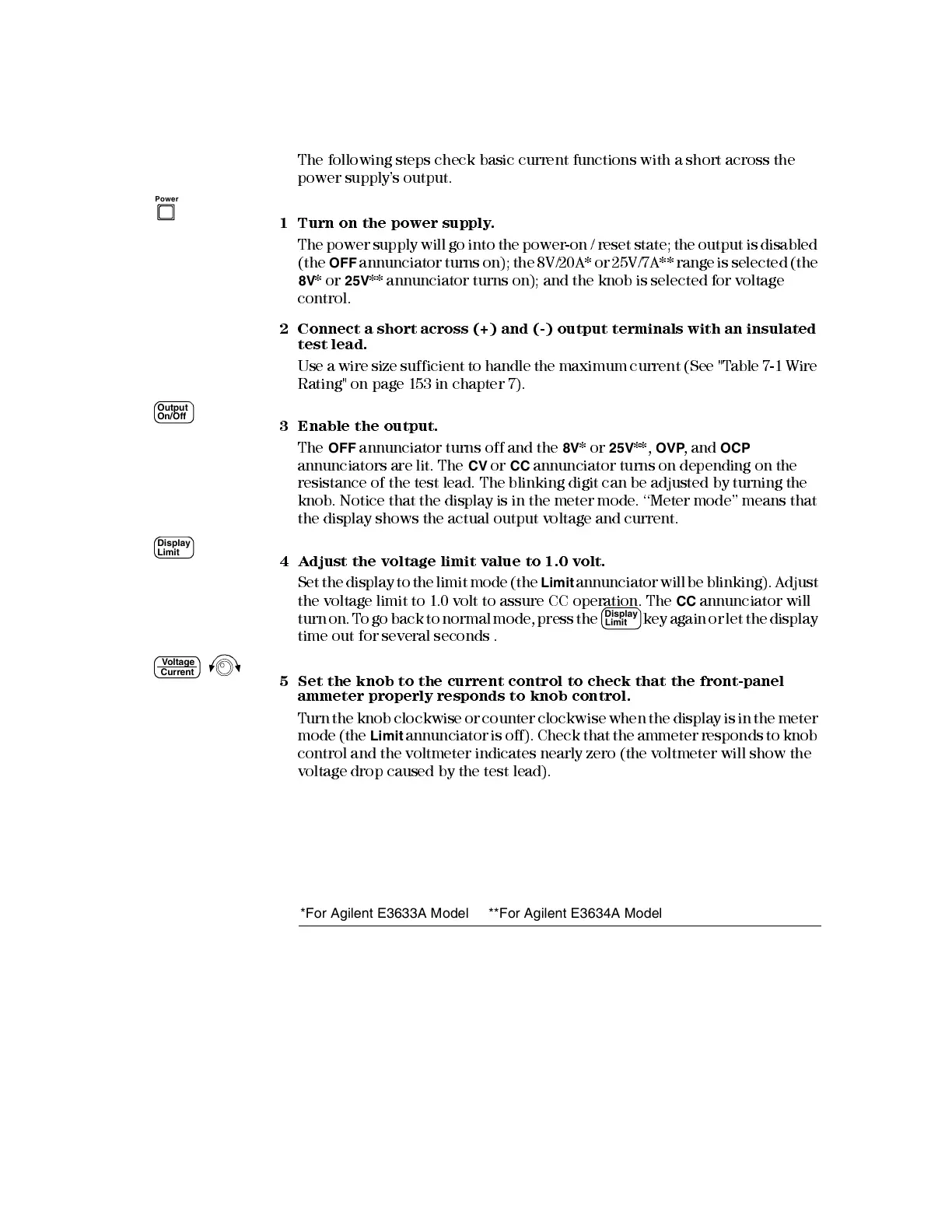
The followi ng steps check basic current functions with a short across the
power supply’s output.
1 Turn on the power supply.
The power supply will go into the power-on / reset state; the output is disabled
(the
OFF
annunciator turns on); the 8V/20A* or 25V/7A** range is select ed (the
8V
* or
25V
** annunciator turns on); and the knob is selected for voltage
control.
2 Conn e c t a s hor t a c r os s (+) a n d (-) outp ut te r mi n a l s w i th a n i n s ul a t ed
test lead.
Use a wire size sufficie nt to handle the maximum current (Se e " Table 7-1 Wire
Rating" on page 153 in chapter 7).
3 Enable the output.
The
OFF
annunciator turns off and the
8V
* or
25V
**,
OVP
, and
OCP
annunciators are lit. The
CV
or
CC
annunciator turns on depending on the
resistance of the test lead. The blinking digit can be adjusted by turning the
knob. Notice that the display is in the meter mode. ‘‘Meter mode’’ means that
the display shows the actual output voltage and current.
4 Adjust the voltage limit value to 1.0 volt.
Set the display to the limit mode (the
Limit
annunciator will be blinking). Adjust
the voltage limit to 1.0 volt to assure CC operation. The
CC
annunciator will
turn on. T o go back to normal mode, press the
key again or let the display
time out for several seconds .
5 Set the knob to the current control to check that the front-panel
ammeter properly responds to knob control.
T urn the knob clockwise or counter clockwise when the display is in the meter
mode (the
Limit
annunciator is off). Check that the ammeter responds to knob
control and the voltmeter indicates nearly zero (the voltmeter will show the
voltage drop caused by the test lead).
Power
Output
On/Off
Display
Limit
Display
Limit
Voltage
Current
*For Agilent E3633A Model **For Agilent E3634A Model

 Loading...


