3 Maintain the ATCA Subrack
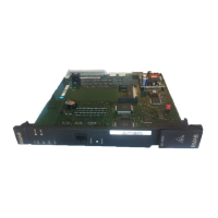
3.5.2 Replace JBXTP
When insert/remove JBXTP wait at least 30 seconds before another
insert/remove operation.
3.5.2.1 Remove JBXTP
To remove a JBXTP board:
1. Open the front doors of the BSC.
2. Connect the anti-static wrist strap.
3. Identify the board to be replaced. Refer to Board/Area/Slot/SBL Mapping
(Section 1.3) for details.
4. Lock the JBXTP board.
Wait until the blue LED is illuminated permanently.
5. Unfasten screws of front plate.
6. Move slowly the ejector handles outwards until you feel resistance.
7. By moving the ejector handles outwards, remove board from shelf.
8. Disconnect the anti-static wrist strap.
9. Close the front doors of the BSC.
3.5.2.2 Insert JBXTP
To insert a JBXTP board:
1. Open the front doors of the BSC.
2. Connect the anti-static wrist strap.
3. Ensure that the top and bottom ejector handles are in the outward position.
4. Insert board into the shelf by placing the top and bottom edges of the board
in the card guides of the shelf. Ensure that the guiding module of shelf
and board are aligned properly.
5. Slide the board into the shelf until you feel resistance. The blue LED
is illuminated.
6. Simultaneously move the top and bottom ejector handles to the inward
position to lock the board to the shelf.
Wait one minute until the blue LED is illuminated permanently.
7. Unlock the JBXTP board.
8. Wait until the blue LED is switched OFF. The switched OFF blue LED
indicates that the board is active.
9. Tighten the front plate screws which secure the board to the shelf.
10. Disconnect the anti-static wrist strap.
11. Using the BSC terminal check if the alarm “FIRMWARE-NOT-UP-TO-DATE”
is reported for the replacement board.
If the alarm is present a firmware upgrade must be performed. Refer to
Update the NE1OE Firmware for the New JBXTP or JBXMUX Boards
(Section 3.5.2.3) for details.
If the alarm is not present continue with the next step.
3BK 21281 AAAA PCZZA Ed.13 33 / 90
 Loading...


