1
8
7
6
5
4
3
2
8 Pin Mini-DIN Cable End 8 Pin Mini-DIN Connector
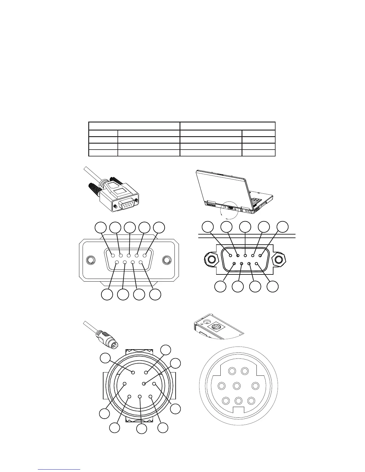
RS-232 / RS-485 Digital Input / Output Signal
To use the RS-232 or RS-485 digital signal, connect the RS-232 / RS-485 Output
Signal (Pin 5), the RS-232 / RS-485 Input Signal (Pin 3) and Ground (Pin 8) to
your serial port as shown below. (See "Serial Communications" on page 39
for details)
9 Pin Serial Connection 8 Pin Mini-DIN Connection
Pin Function Function Pin
5 Ground Ground 8
3 Transmit Receive 3
2 Receive Transmit 5
DB9 to 8-Pin Mini-DIN Connection for RS-232 / RS-485 Signals
Getting Started
 Loading...