EasyManuals Logo

Alicat MC Series User Manual

Alicat MC Series
102 pages
To Next Page IconTo Next Page
To Previous Page IconTo Previous Page
Page #94 background imageLoading...
Page #94 background image
94








520-290-6060 Ph. 520-290-0109 Fax


7641 N Business Park Dr. Tucson, AZ 85743
























Rev. No. Description Date
1
6
5
4
3
2
The above pinout is applicable to all the ow controllers and controllers ordered with
the industrial connector. The availability of di󰀨erent output signals depends on the
ow controller options ordered.
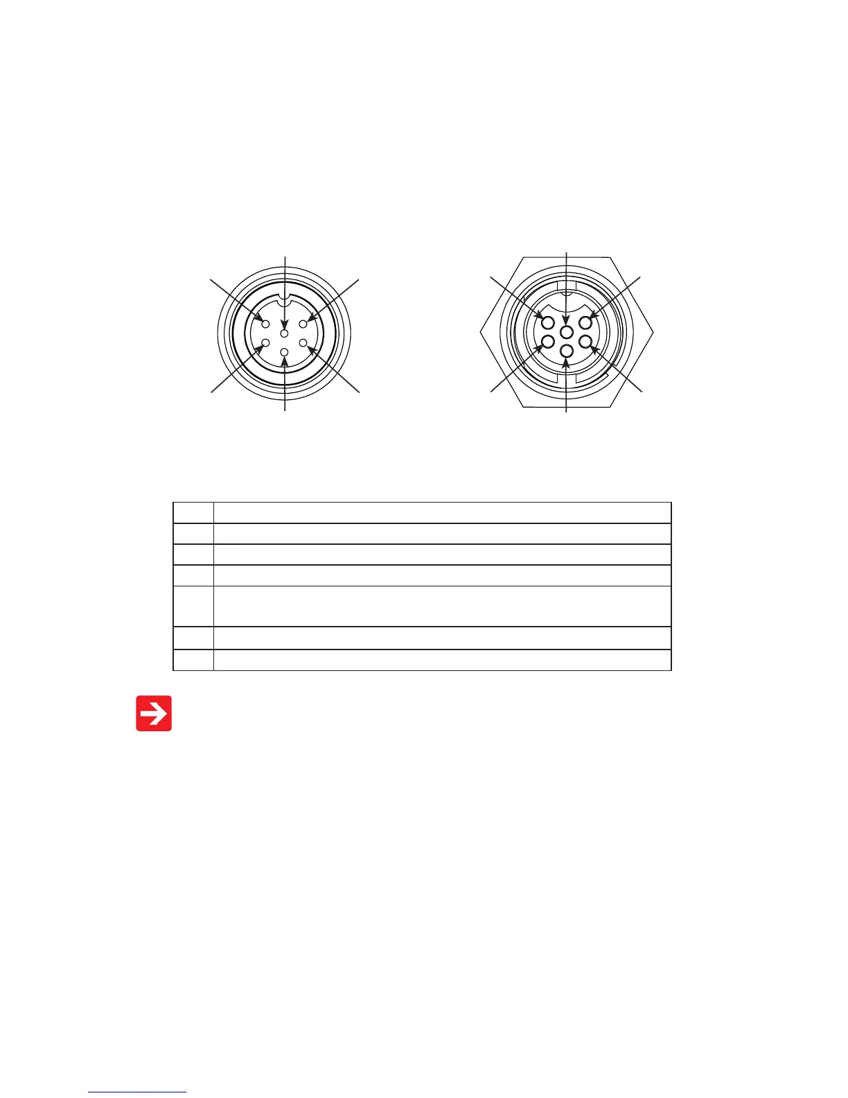
Locking Industrial Connector Pinouts
If your Alicat Instrument was ordered with a Six Pin Locking Industrial
connection, please be sure to reference the following pinout diagram.
Pin Function
1 Power In ( + )
2 RS-232TX / RS-485(+)
3 RS-232RX / RS-485(-)
4 Meters/Gauges = Remote Tare (Ground to Tare)
Controllers = Analog Setpoint Input
5 Ground (common for power, communications and signals)
6 Signal Out (Voltage or Current as ordered)
Male Connector: Cable Female Connector: Device
Optional Pinouts

Table of Contents

Questions and Answers:

Question and Answer IconNeed help?

Do you have a question about the Alicat MC Series and is the answer not in the manual?

Alicat MC Series Specifications

General IconGeneral
BrandAlicat
ModelMC Series
CategoryController
LanguageEnglish