96
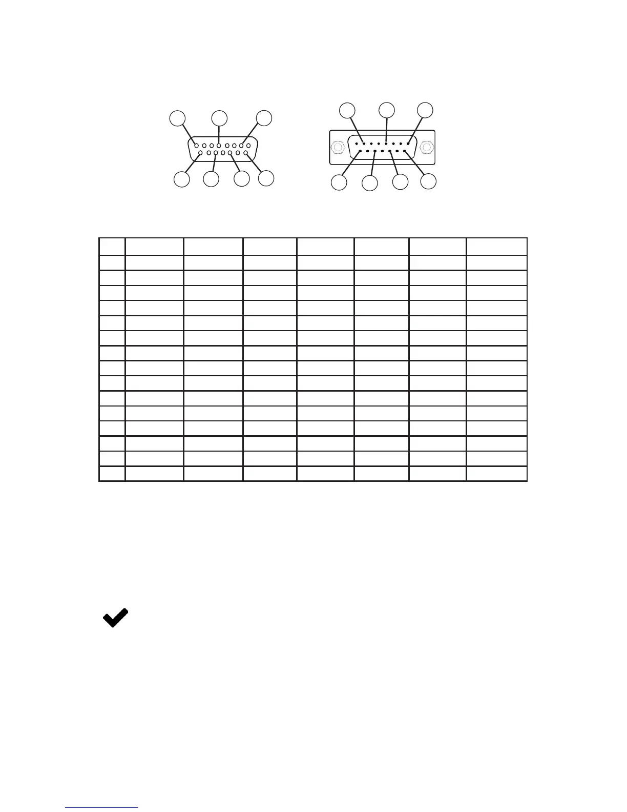
15 pin D-Sub Common Pinouts
If your instrument was ordered with a DB15 connection, be sure to check the calibration label on
the device or the calibration data sheet and reference the appropriate pinout diagram.
Pin DB15 DB15A DB15B DB15H DB15K DB15O DB15S
1 Ground Ground Ground NC NC Ground Ground
2 Analog Out Analog Out Analog Out RX (-) Analog Out NC Analog Out
3 Ground Analog In NC NC NC NC NC
4 NC Ground NC NC NC Analog Out NC
5 Power In Ground Power In Ground Ground Power In Ground
6 NC Ground NC Analog Out NC NC NC
7 NC Power In NC Ground Power In Analog In NC
8 Analog In TX (+) Analog In NC Analog In NC Analog In
9 Ground Ground Ground NC Analog Out 2 Ground Ground
10 Ground NC Ground Analog Out 2 NC Ground Ground
11 Analog Out 2 NC Analog Out 2 Power In Ground Analog Out 2 Analog Out 2
12 NC Analog Out 2 NC Ground Ground NC RX (-)
13 RX (-) NC NC NC RX (-) NC Power In
14 Ground NC RX (-) Analog In TX (+) RX (-) TX (+)
15 TX (+) RX (-) TX (+) TX (+) Ground TX (+) Ground
Analog In = setpoint for controllers or remote tare function for meters
Analog Out = 0-5 Vdc Output Signal (or 0-10 Vdc optional)
Analog Out 2 = 5.12Vdc or Optional Secondary Analog Output
TX (+) = Serial RS-232TX or RS-485(+)
RX (-) = Serial RS-232RX or RS-485(-)
NC = Not Connected
Power In = (+Vdc)
Ground = Common for power, digital communications, analog signals and alarms
Individual pinouts available at www.alicat.com/pinout
Due to variance in cable manufacturing, please identify proper wiring/pins via
continuity check & color when using blunt cut multi-strand cables.
Female Connector Front View
8
15
13
11
9
2
5
Male Connector Front View
8
15
13
11
9
2
5

 Loading...