Rockwell Automation Publication 1444-UM001D-EN-P - June 2018 129
Measurement Definition Chapter 4
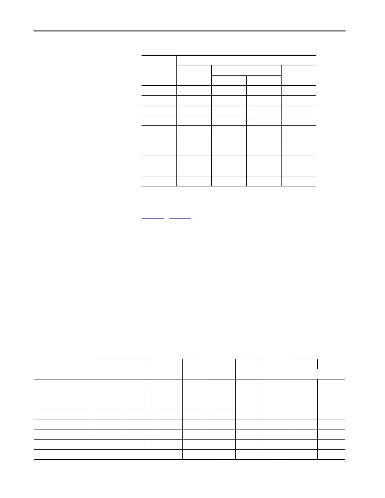
Tab le 23…Table 27 include the Decimation menu selections for each of the
selectable Sample Rate Divide (SRD) values (selected by the ADC FMAX
menu). The table shows the decimation value that is written to the
configuration assembly, and the FFT FMAX that the measurement can
output.
The menus do not provide selections for the 255 possible decimation values.
Rather, the menus present only selected decimated values that represent
relatively uniform increments from about 30 Hz to the ADC FMAX.
If the Measurement Type (Hardware Configuration page) is either of the
Aeroderivative types, then the Primary Path FMAX selections are the same as
the types that are for listed for the Alternate Path. This similarity is due to the
applied -60 dB/octave filter, vs. the standard -24 dB/octave primary path filter
that is used for the aeroderivative measurement type.
Table 22 - Data Source Options for Each Measurement
Measurement Signal Sources
ADC Out Primary Path Alternate
Path
(2)
Mid-Filter Post-Filter
gSE
Tracking Filters
Overall (2) (3)
Not 1x
SMAX
Shaft Absolute
TWF (1)
(1)
(3) (4) (5)
FFT (1)
(1)
(3) (4) (5)
FFT Bands (1)
(1)
(3) (4) (5)
Demand Data (1)
(1)
(3) (4) (5)
(1) ADC Out is not available for 40 kHz personalities.
(2) Alternate Path is available only when enabled (not “Off”)
Table 23 - Primary Path Decimation Menu: SRD 1…5
Primary Path
Dec FMAX Dec FMAX Dec FMAX Dec FMAX Dec FMAX
SRD = 1 SRD = 2 SRD = 3 SRD = 4 SRD=5
Dec < 5 is not allowed - 1 20600 1 13733 1 10299 1 8240
5 2747 2 3433 2 2289 2 1717 2 1373
6 2289 3 2289 3 1526 3 1144 3 916
9 1526 4 1717 4 1144 4 858 4 687
12 1144 5 1373 5 916 5 687 5 549
13 1056 6 1144 6 763 6 572 6 458
14 981 7 981 7 654 7 490 7 392
15 916 8 858 8 572 9 381 9 305
 Loading...