148 Rockwell Automation Publication 2094-UM001J-EN-P - March 2017
Chapter 6 Configure and Start the Kinetix 6000 Drive System
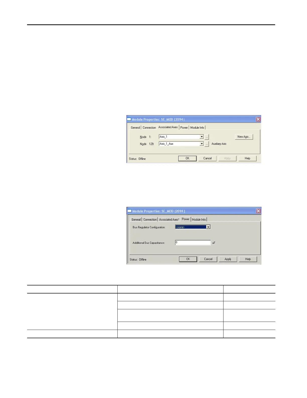
11. Click Apply.
The Auxiliary Axis (Node 129) is configured identical to Node 1 by
clicking New Axis and creating a new tag.
12. Click Apply if you made changes.
13. Click the Power tab.
14. From the Bus Regulator Catalog Number pull-down menu, choose the
shunt option appropriate for your actual hardware configuration.
TIP With drive firmware revision 1.80 or later, and the Logix Designer
application or RSLogix 5000 software, version 13 or later, it is possible to
configure the Auxiliary Axis feedback port as a Feedback Only axis. With this
feature, you can configure each IAM inverter or AM module to appear as two
axes/nodes on the Sercos ring. The base node is the servo axis using the
motor feedback, and the base node (plus 128) is a feedback-only axis that
uses the auxiliary feedback port.
Auxiliary feedback is not supported by the Kinetix 6000M IDM units.
If your IAM module is And your hardware configuration includes this shunt option Then choose
Configured as an IAM module or
common-bus leader IAM module
(1)
Internal shunt resistors only Internal or <none>
Bulletin 2094 (rail mounted) shunt module 2094-BSP2
Bulletin 1394 passive shunt module (connected to the 2094-BSP2 shunt
module)
1394-SRxxxx
External active shunt module Internal or <none>
Configured as a common-bus follower IAM module
(2)
N/A. Shunts are disabled on follower IAM module CommonBus Follow
(1) Drive does not accept Internal, <none>, 2094-BSP2, or 1394-SRxxxx selection if DC bus voltage is present without having three-phase power applied.
(2) Drive does not accept CommonBus Follow selection if three-phase power or DC bus power is applied.
 Loading...


