104 Rockwell Automation Publication 2094-UM001J-EN-P - March 2017
Chapter 5 Connect the Kinetix 6000 Drive System
Wiring the Safe Torque-off (STO) Connector
This example applies to any IAM or AM module equipped with the torque-off
(STO) connector.
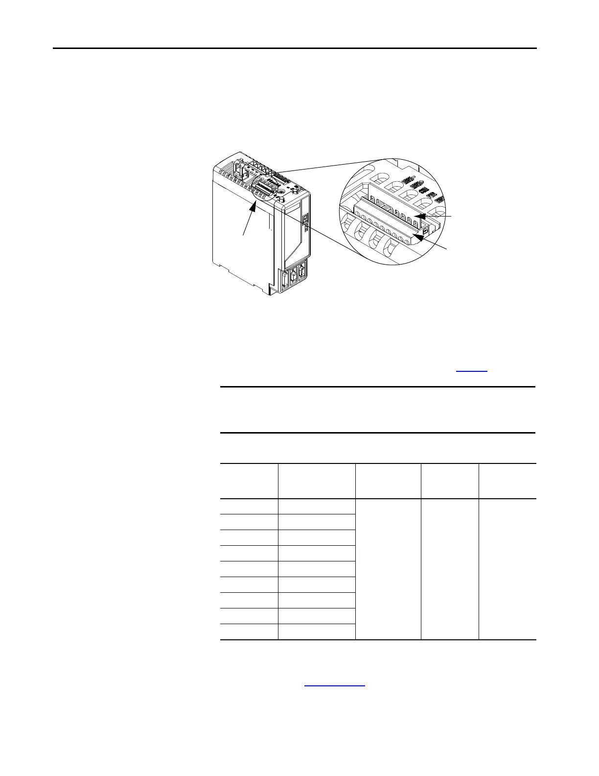
Figure 53 - IAM/AM Module (STO connector)
Each IAM and AM module ships with the (9-pin) wiring-plug header and
motion-allowed jumper installed in the safe torque-off connector. With the
motion-allowed jumper installed, the safe torque-off feature is not used.
Pinouts for the torque-off (STO) connector are shown on page 60
.
Table 69 - Safe Torque-off (STO) Connector
To wire the safe torque-off connector in single axis or multi-axis
configurations, refer to the Kinetix Safe Torque-off Feature Safety Reference
Manual, publication GMC-RM002
.
Motion-allowed Jumper
Wiring Plug Header
Kinetix 6000
IAM/AM Module
(AM module is shown)
Safe Torque-off
(STO) Connector
IMPORTANT Pins STO-8 and STO-9 (24V+) are used by only the motion-allowed jumper.
When wiring to the wiring-plug header, the 24V supply must come from an
external source.
STO Pin Signal
Recommended
Wire Size
mm
2
(AWG)
Strip Length
mm (in.)
Torque Value
N•m (lb•in)
1FDBK2+
0.75 (18)
(stranded wire with
ferrule)
1.5 (16)
(solid wire)
7.0 (0.275) 0.235 (2.0)
2FDBK2-
3FDBK1+
4FDBK1-
5 SAFETY ENABLE2+
6 SAFETY ENABLE-
7 SAFETY ENABLE1+
824V +
924V_COM
 Loading...


