Rockwell Automation Publication 2094-UM001J-EN-P - March 2017 47
Plan the Kinetix 6000 Drive System Installation Chapter 2
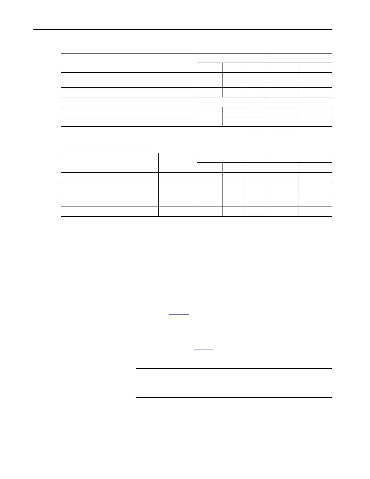
Table 18 - IDM Power Interface Module (IPIM)
Table 19 - Resistive Brake Module (RBM)
Noise Reduction Guidelines for Drive Accessories
Refer to this section when mounting an AC (EMC) line filter or external shunt
module for guidelines designed to reduce system failures caused by excessive
electrical noise.
AC Line Filters
Observe these guidelines when mounting your AC (EMC) line filter (refer to
the figure on page 44
for an example):
• Mount the AC line filter on the same panel as the Kinetix 6000 drive
and as close to the power rail as possible.
• Good HF bonding to the panel is critical. For painted panels, refer to
the examples on page 35
.
• Segregate input and output wiring as far as possible.
Wire/Cable
Zone Method
Very Dirty Dirty Clean Ferrite Sleeve Shielded Cable
Hybrid DC bus power, control power,
inter-module communication, and Safe Torque Off
(1)
XX
Enable input X X
Fiber-optic No restrictions
Ethernet network X X
IDM network
(1)
XX
(1) There is no option for making your own hybrid power or IDM network cables.
Wire/Cable Connections
Zone Method
Very Dirty Dirty Clean Ferrite Sleeve Shielded Cable
Resistive brake module coil power TB3-6 and TB3-7 X
Resistive brake module I/O
TB1-1…TB1-5
and TB3-8
X
Resistive brake module drive and motor power TB1 and TB2 X X
230V power TB4 X
IMPORTANT CE test certification applies only to AC line filter and single power rail.
Sharing a line filter with multiple power rails can perform satisfactorily, but
the user takes legal responsibility.

 Loading...


