238 Rockwell Automation Publication 2094-UM001J-EN-P - March 2017
Appendix D Configure the Load Observer Feature
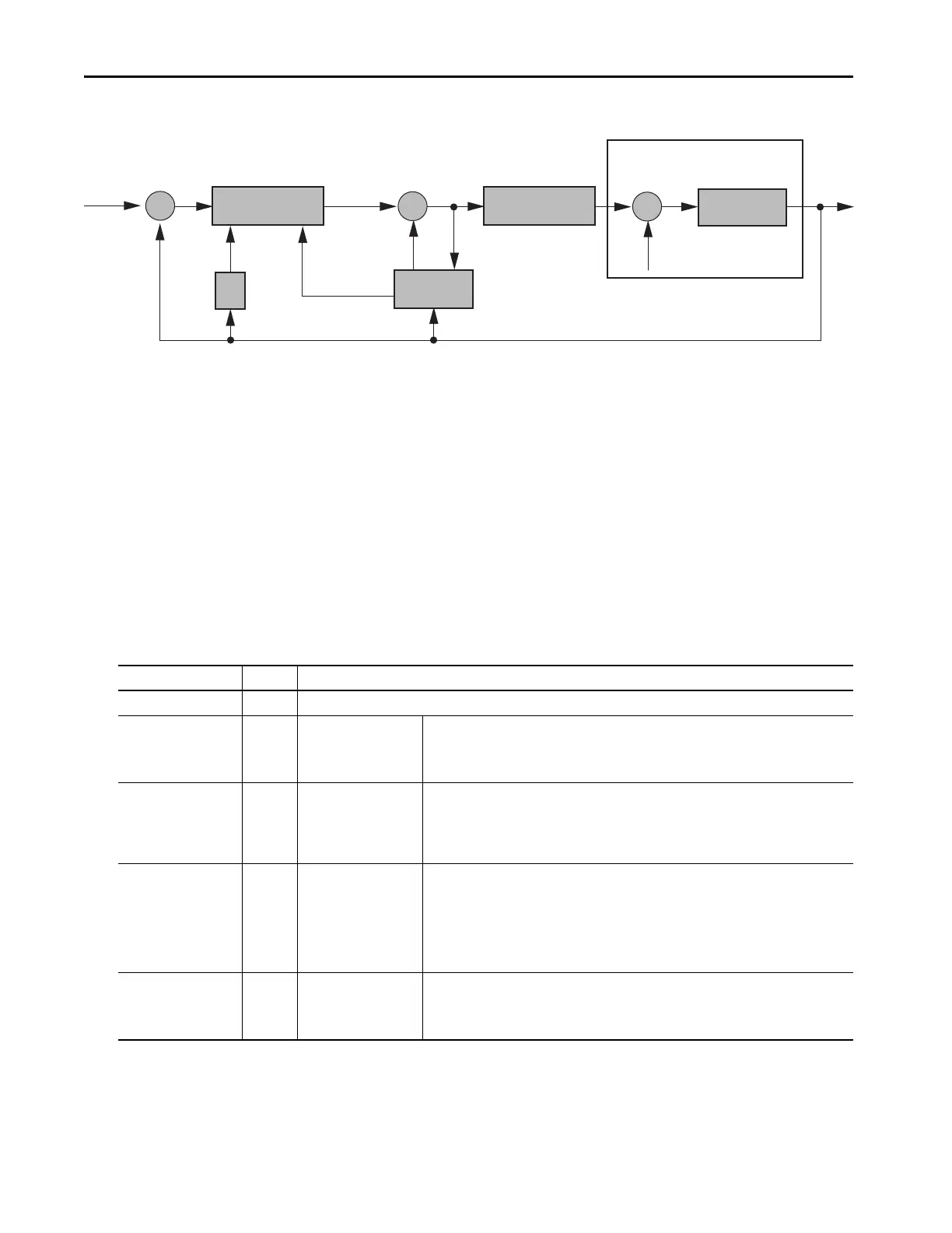
Figure 114 - Load Observer and Control Loop Signals Relationship Block Diagram
Load observer also generates a Velocity Estimate signal that you can apply to
the velocity loop. The Velocity Estimate has less delay than the Velocity
Feedback signal derived from the actual feedback device. It also helps to reduce
high frequency output noise caused by load observer's aggressive action on the
acceleration reference. Together, load observer with the Velocity Estimate
setting provides the best overall performance.
Configuration
You can configure the load observer feature in a variety of ways by writing to a
set of configuration IDN parameters. The overall behavior of load observer is
controlled by Load Observer Configuration (IDN P-431). This parameter is
used to select the load observer mode. It can be set to the following values.
Table 125 - Load Observer Modes
Velocity Estimate
Torque Estimate
Position Feedback
Servo Drive
Mechanics
Unloaded Motor
Pos
Cmd
Load Observer
Control Loops
Power Conversion
Acceleration Reference
Torque Load
Fs
Mode Value Description
Disabled (default) 0 Load Observer is inactive
Load Observer Only 1
Provides a Torque
Estimate only
This setting is a filtered acceleration feedback with the addition of integral action in the
acceleration forward path that is active below the observer bandwidth. This greatly increases the
disturbance rejection properties (stiffness) over the acceleration feedback setting. However, it is
also fairly aggressive and the observer bandwidth must be decreased for stable operation.
Load Observer with
Velocity Estimate
2
Standard Operation:
Provides Torque and
Velocity Estimates
This setting combines the best of the Load Observer Only and Velocity Estimate Only settings.
Separately, load observer removes error, but increases phase lag and is fairly aggressive, whereas
velocity estimate provides a smooth response and reduces phase lag, but creates error. Together,
they remove error and provide a smooth response. Load observer performs well in situations that
require adapting to changing inertia and velocity integrator anti-windup.
Velocity Estimate Only 3
Provides a Velocity
Estimate only
This setting creates a filtered velocity feedback signal that is void of phase lag. Less phase lag
(delay around the loop) allows for higher performance. However, the signal is modeled at
frequencies above the observer bandwidth, producing error in velocity feedback. This generates a
fictitiously lower velocity error since velocity error equals velocity command minus velocity
feedback. Nevertheless, the steady state error disappears when used in position mode with either
the position integrator or the observer integrator. This configuration is not desirable for Velocity
mode applications.
Acceleration Feedback 4
Provides acceleration
feedback by disconnecting
Acceleration Reference to
load observer
This setting creates a filtered acceleration feedback signal. This setting is fairly aggressive and the
observer bandwidth must be decreased significantly for stable operation. The Load Observer Only
setting is similar, but without the additional phase lag (delay) created by necessary filtering.
 Loading...


