Rockwell Automation Publication 2094-UM001J-EN-P - March 2017 193
Interconnect Diagrams Appendix A
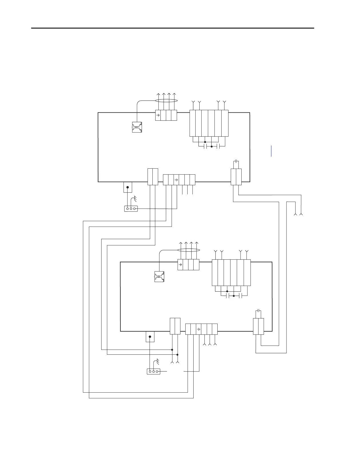
DC Common Bus Wiring Examples
Figure 90 - Leader IAM Module with Single Follower IAM Module
CONT EN-
CONT EN+
W
V
U
DC-
DC+
L3
L2
L1
CTRL 2
CTRL 1
1
2
1
2
3
4
5
6
1
2
6
5
4
3
2
1
4
3
2
1
CONT EN-
CONT EN+
W
V
U
DC-
DC+
L3
L2
L1
CTRL 2
CTRL 1
1
2
1
2
3
4
5
6
1
2
6
5
4
3
2
1
4
3
2
1
MBRK -
MBRK +
COM
PWR
DBRK -
DBRK +
N.C.
N.C.
N.C.
MBRK -
MBRK +
COM
PWR
DBRK -
DBRK +
Single-phase Input
95…264V AC RMS
Notes 1, 2
Three-phase Input from LIM
or Input Power Contactor (M1)
195…264V AC RMS
or 324…528V AC RMS
Notes 1, 2, 7, 8
Control Power
(CPD) Connector
Power Rail
Ground Stud
DC Bus
and
Three-phase
Input (IPD)
Connector
Contactor Enable
(CED) Connector
Note 14
Motor/Resistive
Brake (BC) Connector
Three-phase
Motor Power
Connections
Note 16
Cable Shield
Clamp
Note 10
Bonded Cabinet
Ground Bus*
Control Power
(CPD) Connector
Power Rail
Ground Stud
DC Bus
and
Three-phase
Input (IPD)
Connector
Contactor Enable
(CED) Connector
Note 14
Motor/Resistive
Brake (BC) Connector
Three-phase
Motor Power
Connections
Note 16
Cable Shield
Clamp
Note 10
Bonded Cabinet
Ground Bus*
Motor Power
(MP) Connector
Motor Power
(MP) Connector
* Indicates User Supplied Component
2094-ACxx-Mxx-x or
2094-BCxx-Mxx-x
Common-bus Follower
IAM Module
2094-ACxx-Mxx-x or
2094-BCxx-Mxx-x
Common-bus Leader
IAM Module
Wire the leader and follower IAM
contactor enable terminals in series
with the control string or LIM I/O.
Refer to table on page 188
for note information.
 Loading...


