100 Rockwell Automation Publication 2094-UM001J-EN-P - March 2017
Chapter 5 Connect the Kinetix 6000 Drive System
Wiring the IAM/AM Module
Connectors
This section provides examples and wiring tables to assist you in making
connections to the IAM and AM modules.
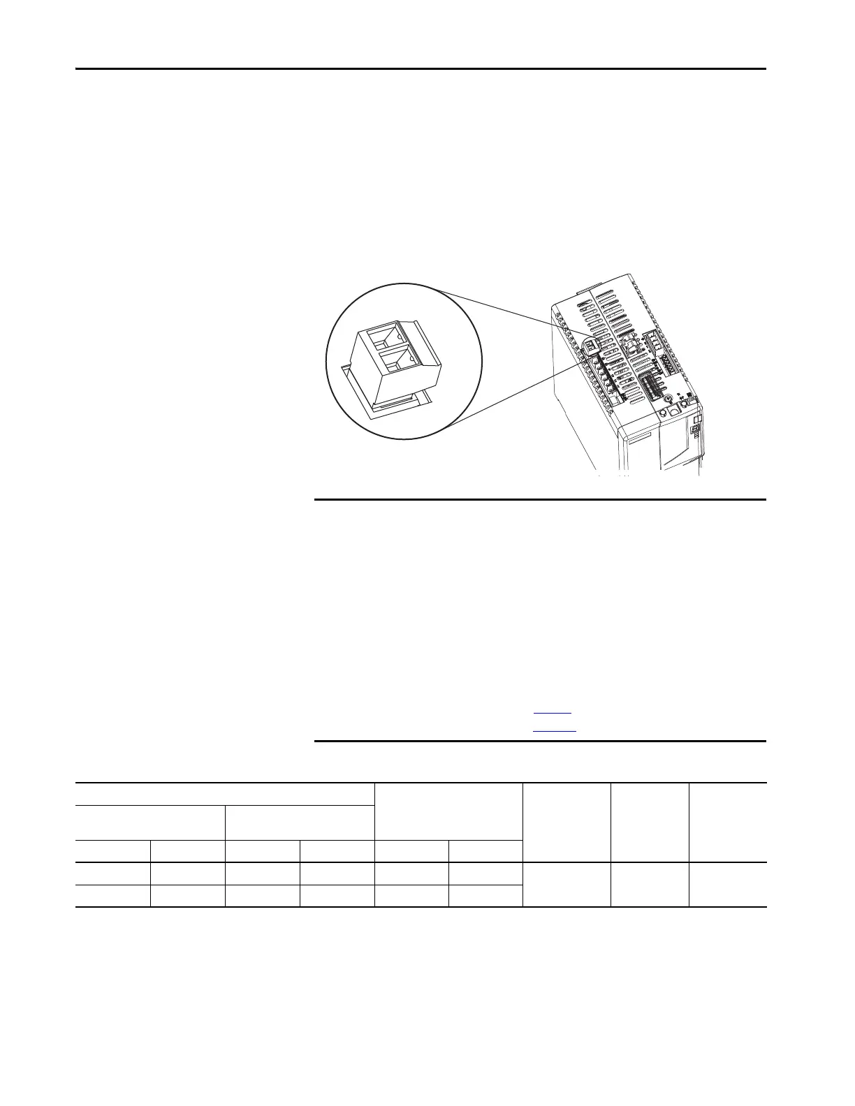
Wire the Control Power (CPD) Connector
This example applies to any IAM, leader IAM, or follower IAM module.
Figure 49 - IAM Module (CPD connector)
Table 63 - Control Power (CPD) Connector
Kinetix 6000
IAM Module, Top View
IMPORTANT The 2094-AL75S, 2094-BL75S, and 2094-XL75S-C2 LIM modules can supply
input power for up to eight axes. The 2094-XL75S-C1 LIM module can
supply up to sixteen axes.
The IPIM module control power load must be calculated for Kinetix 6000M
systems and the LIM module control power input must have a sufficient
current rating. If no LIM module can support the current requirement, then
discrete components must be used.
The National Electrical Code and local electrical codes take precedence over
the values and methods provided. Implementation of these codes is the
responsibility of the machine builder.
Refer to Control Power on page 77
for more information and IAM Module
(without LIM module) on page 192
for the interconnect drawing.
CPL Connector (LIM module) or Other Single-phase Input
CPD Connector
(IAM module)
Recommended
Wire Size
mm
2
(AWG)
Strip Length
mm (in.)
Torque Value
N•m (lb•in)
2094-ALxxS, 2094-BLxxS, or
2094-XL75S-Cx LIM Module
2094-AL09 and 2094-BL02
LIM Module
CPL Pin Signal CPL Pin Signal CPD Pin Signal
1 CTRL 1 2 L1 1 CTRL 2
2.5 (14) 10 (0.38)
0.5…0.6
(4.4…5.3)
2 CTRL 2 1 L2/N 2 CTRL 1
 Loading...


