Rockwell Automation Publication 2094-UM001J-EN-P - March 2017 69
Connector Data and Feature Descriptions Chapter 4
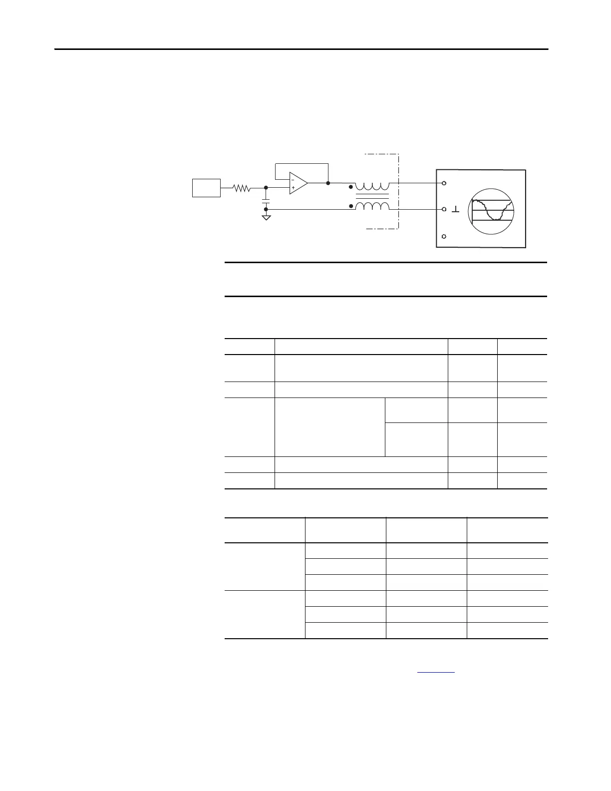
Analog Outputs
The IAM and AM modules include two analog outputs (IOD-23 and
IOD-25) that you can configure through software to represent drive variables.
Figure 31 - Analog Output Circuit
Table 39 - Analog Output Specifications
Table 40 - Linear Scaling Specifications
For configuration/set up of the analog outputs, refer to Configure Drive
Parameters and System Variables beginning on page 162
.
OscilloscopeKinetix 6000 IAM/AM
Module
(second channel not shown)
IMPORTANT Output values can vary during powerup until the specified power supply
voltage is reached.
Parameter Description Min Max
Resolution
Number of states that the output signal is divided into,
which is 2
(to the number of bits)
.
– ±11 bits
Output current Current capability of the output. 0 +2 mA
Output signal
range
Range of the output voltage.
2094-xCxx-Mxx and
2094-xMxx drives
0+5V
2094-xCxx-Mxx-S
and 2094-xMxx-S
drives
0 +10V
Offset error Deviation when the output is expected to be at 0V. – 1 mV
Bandwidth Frequency response of the analog output DC 7.2k Hz (3 db)
Drive Cat. No.
Speed
rpm
Value
V DC
Torque
%
2094-xCxx-Mxx
or 2094-xMxx
10,000 5.0 1000
02.50
-10,000 0 -1000
2094-xCxx-Mxx-S
or 2094-xMxx-S
10,000 10.0 1000
05.00
-10,000 0 -1000
 Loading...


