Rockwell Automation Publication 2094-UM001J-EN-P - March 2017 189
Interconnect Diagrams Appendix A
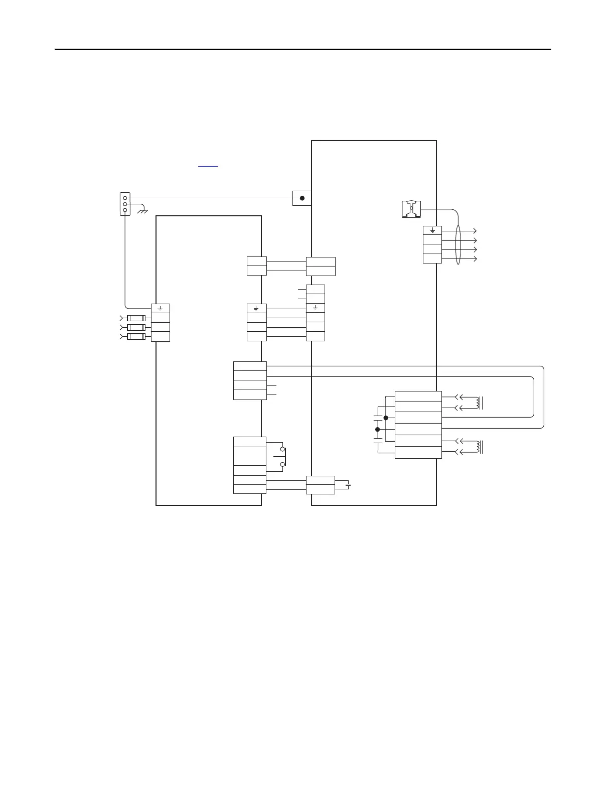
Power Wiring Examples
These examples apply to power wiring configurations with and without the
Bulletin 2094 line interface module (LIM), DC common bus wiring, and
shunt module wiring.
Figure 87 - Single IAM Module with 2094-AL09 or 2094-BL02 LIM Module
L3
L2
L1
DC-
DC+
L3
L2
L1
L2
L1
CTRL 2
CTRL 1
L3'
L2'
L1'
1
2
1
2
3
4
5
6
1
2
BR-
MBRK -
MBRK +
COM
PWR
DBRK -
DBRK +
BR-
MBRK_PWR
MBRK_COM
MBRK_PWR
MBRK_COM
CONT EN-
CONT EN+
W
V
U
24-26
13
20-22
4
4
3
2
1
IO_PWR
COIL_A1
IO_COM
COIL_A2
1
2
3
4
BR+
BR+
1
2
6
5
4
3
2
1
Control Power
(CPD) Connector
* Indicates User Supplied Component
Contactor Enable
(CED) Connector
Note 14
Motor Brake
Connections
Resistive Brake
Connections
24V DC Output
(PSL) Connector
Motor/Resistive
Brake (BC) Connector
Three-phase
Motor Power
Connections
Note 16
Motor Power
(MP) Connector
Cable Shield
Clamp
Note 10
2094-ACxx-Mxx-x or
2094-BCxx-Mxx-x
IAM Module
Bonded Cabinet
Ground Bus*
VAC LINE Three-phase
(IPL) Input
195…264V AC RMS
or 324…528V AC RMS
Note 1
Power Rail
Ground Stud
Ground
VAC LOAD Three-phase
(OPL) Output
195…264V AC RMS
or 324…528V AC RMS
Note 1
STOP *
I/O (IOL)
Connector
Notes 13, 14
2094-AL09 or 2094-BL02
Line Interface Module
DC Bus
and
Three-phase
Input (IPD)
Connector
Single-phase (CPL) Output
195…264V AC RMS
Note 1
Input Fusing *
Refer to table on page 188
for note information.
 Loading...


