270 Rockwell Automation Publication 2094-UM001J-EN-P - March 2017
Appendix G RBM Module Interconnect Diagrams
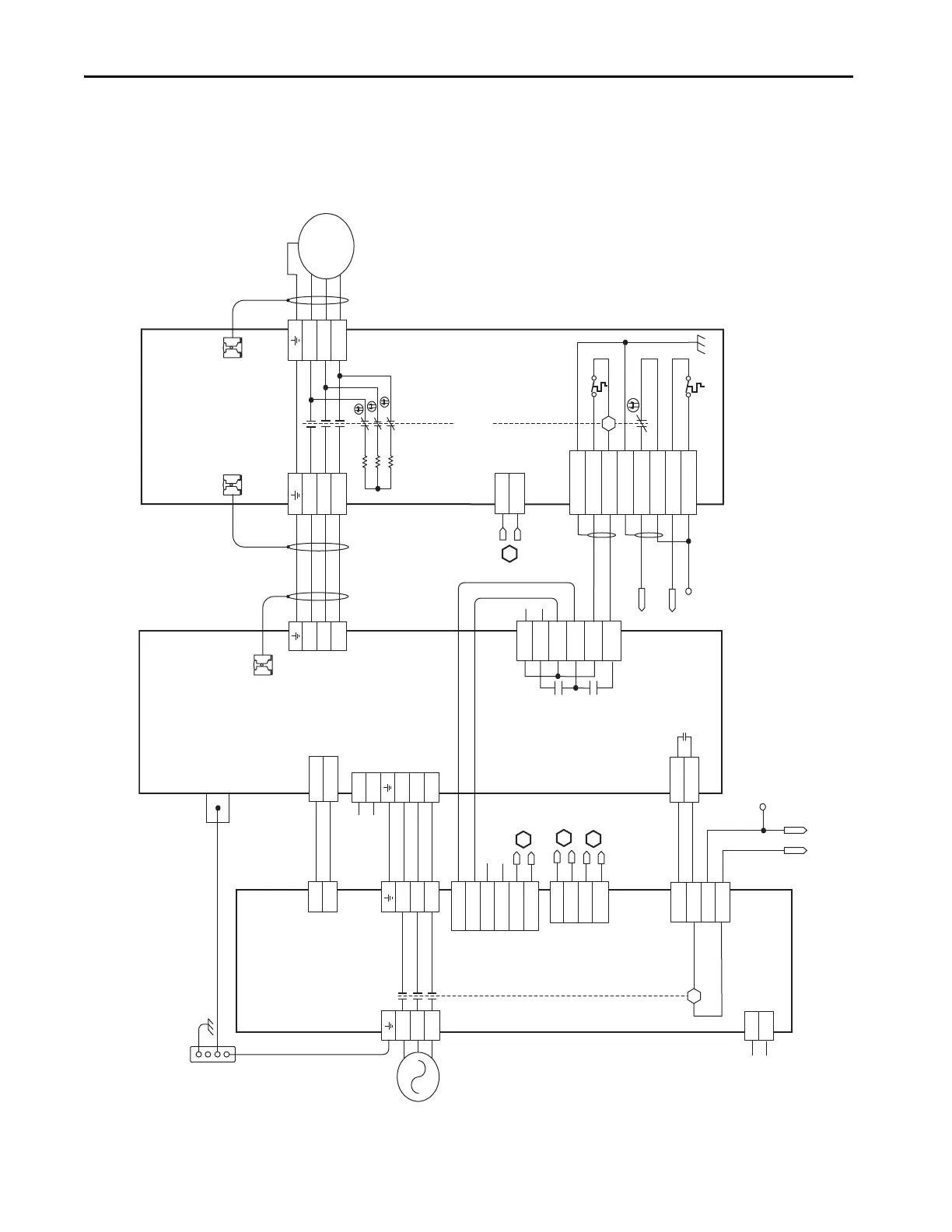
RBM Module Wiring
Examples
This example diagram shows 2094-xCxx-Mxx-S and 2094-xMxx-S drives
(with safe torque-off ) and 2094-ALxxS, 2094-BLxxS, and 2094-XL75S LIM
modules wired with the Bulletin 2090 RBM module.
Figure 124 - RBM Wiring Example
T2
T1
K
4
3
2
1
4
3
2
1
D
C
B
A
IO_PWR1
BRKTMP0
CONT EN-
CONT EN+
W
V
U
L3
L2
L1
2, 4, 6
8
1, 3, 5
7
DC-
DC+
L3
L2
L1
CTRL 2
CTRL 1
L3'
L2'
L1'
1
2
1
2
3
4
5
6
1
2
6
5
4
3
2
1
4
3
2
1
W_DRIVE
V_DRIVE
U_DRIVE
W_MTR
V_MTR
U_MTR
SHIELD
COIL_A2
COIL_A1
SHIELD
CONSTAT_42
CONSTAT_41
TS_22
TS_21
MBRK -
MBRK +
COM
PWR
DBRK -
DBRK +
8
7
6
5
4
3
2
1
K
IO_COM1
COIL_E2
IO_PWR1
COIL_E1
BRKSTAT0
IO_PWR1
L1
L2
L3
AUX3
AUX2
AUX1
R3
R2
R1
W
V
U
GND
M
AUX4
1
2
3
4
5
6
1
2
2
1
L2
L1
IO_PWR2
IO_COM2
IO_PWR2
IO_COM2
IO_PWR2
IO_COM2
1
2
3
4
AUX1_L1
AUX1_L2
AUX2_L1
AUX2_L2
B
B
A
CTRL 2
CTRL 1
1
2
3
4
C
L1
L2/N
1
2
1
2
3
4
Note 1
Note 4
Note 1
Auxiliary 230V AC
Input (TB4) Connector
(2090-XB120-xx only)
Kinetix 6000
Integrated Axis Module
2094-ACxx-Mxx-S or
2094-BCxx-Mxx-S
(Axis_0)
Cable Shield
Clamp
2090-XXNRB-14F0P7
RBM to Drive Interface Cable
Note 2
Motor Connections
(TB2) Connector
Drive Connections
(TB1) Connector
I/O Connections
(TB3) Connector
Refer to the wiring examples in
Appendix A for motor power
cable catalog numbers.
Note 2
Motor/Resistive
Brake (BC) Connector
Motor Power
(MP) Connector
Cable Shield
Clamp
Cable Shield
Clamp
Motor Power
Connections
Bulletin 2090
Resistive Brake Module
2090-XBxx-xx
(RBM_0)
Contactor Enable
(CED) Connector
Note 1
Note 3
Control Power
(CPD) Connector
Power Rail
Ground Stud
DC Bus
and
Three-phase
Input (IPD)
Connector
24V DC Output
(P1L) Connector
Three-phase Input
(IPL) Connector
I/O (IOL)
Connector
230V AC Output
(P2L) Connector
Three-phase Output
(OPL) Connector
Single-Phase Output
(CPL) Connector
Bonded Cabinet
Ground Bus*
* Indicates User Supplied Component
Bulletin 2094
Line Interface Module
2094-ALxxS, 2094-BLxxS,
or 2094-XL75S-C2
230V AC Auxiliary
Input Power
(APL) Connector
To external customer-supplied
Drive Enable signal.
 Loading...


