Note 1
Note 4
Note 1
Auxiliary 230V AC
Input (TB4) Connector
(2090-XB120-xx only)
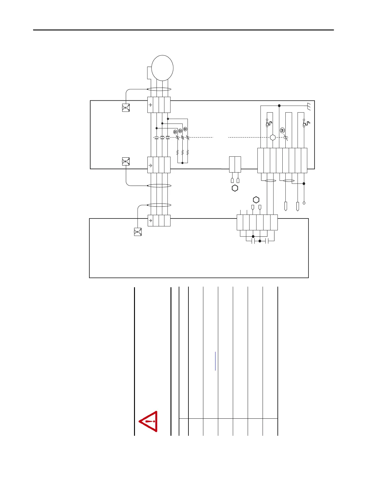
Kinetix 6000
Axis Module
2094-AMxx-S or
2094-BMxx-S
(Axis_1)
Cable Shield
Clamp
2090-XXNRB-14F0P7
RBM to Drive Interface Cable
Note 2
Motor Connections
(TB2) Connector
Drive Connections
(TB1) Connector
I/O Connections
(TB3) Connector
Motor/Resistive
Brake (BC) Connector
Motor Power
(MP) Connector
Cable Shield
Clamp
Cable Shield
Clamp
Motor Power
Connections
Bulletin 2090
Resistive Brake Module
2090-XBxx-xx
(RBM_1)
Note 1
Note 3
* Indicates User Supplied Component
Refer to the wiring examples in
Appendix A for motor power
cable catalog numbers.
Note 2
ATTENTION: The National Electrical Code and local
electrical codes take precedence over the values
and methods provided. Implementation of these
codes is the responsibility of the machine builder.
Note Information
1 Cable shield clamp must be used to meet CE requirements. No external
connection to ground required.
2 For motor cable specifications, refer to the Kinetix Motion Accessories
Technical Data, publication KNX-TD004.
3 The BRKTMP0 signal can be wired to a ControlLogix® input as overtemp
warning in user program.
4 Firmware revision 1.071 or later is required to use the DBRK outputs on the
Kinetix 6200 and Kinetix 6500 IAM or AM module.
5 Set the safety relay time delay beyond the time required to stop and disable
the axis when running at full speed.
6 Drive Enable Input Checking must be selected when configuring Axis
Properties in the Logix Designer application.
 Loading...


