Process Control Instructions
178 Rockwell Automation Publication 1756-RM006K-EN-P - November 2018
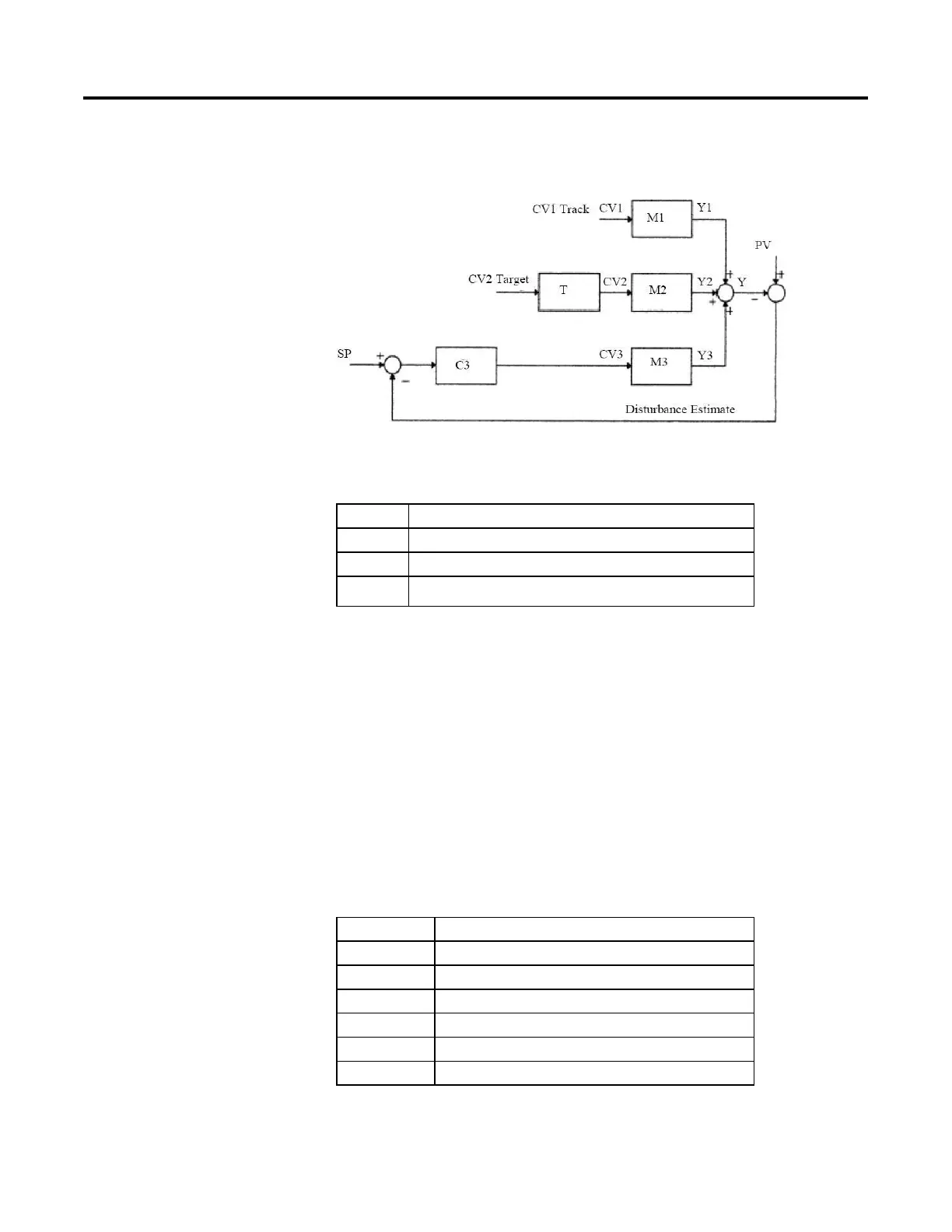
The following illustration is an example of the Coordinated Control closed loop
configuration.
In this example, CV1 is in Manual mode, CV2 is driven to its target value, and
CV3 is the active control. The following table describes this example in detail.
Name Description
CV1 Is in Manual mode
CV2 Is driven to its target value (CV2 = Target1stCV)
CV3 Is the active control (CV3 = Act1stCV)
This example could be a heat cooled system with a feed forward where:
• CV1 is feed forward;
• CV2 is cooling;
• CV3 heating.
Since CV1 is in Manual mode, CV3 target value as the lowest priority goal cannot
be accomplished. PV will be maintained at the setpoint by using CV3, and at the
same time CV2 will be driven to its target value (2nd priority goal).
If the operator changes the CV1 manual value, the control variable will take the
change into account when calculating new CV3 and CV2.
M1 CV1 - PV First order lag with deadtime model
M2 CV2 - PV First order lag with deadtime model
M3 CV3 - PV First order lag with deadtime model
T Target Response
C3 Model based algorithm to control PV by using CV3
Y1, Y2, Y3 Model outputs of M1, M2, M3
Y PV prediction
 Loading...

