Process Control Instructions
24 Rockwell Automation Publication 1756-RM006K-EN-P - November 2018
Rate-of-change Alarm
The rate-of-change (ROC) alarm compares the change of the input over the
ROCPeriod to the rate-of-change limits. The ROCPeriod provides a type of
deadband for the rate-of-change alarm. For example, define an ROC alarm limit of
2
O
F/second with a period of execution of 100 ms. If you use an analog input
module with a resolution of 1
O
F, every time the input value changes, an ROC
alarm is generated because the instruction calculates an effective rate of
10°F/second. However, enter an ROCPeriod of 1 sec and the instruction only
generates an alarm if the rate truly exceeds the 2
O
F/second limit.
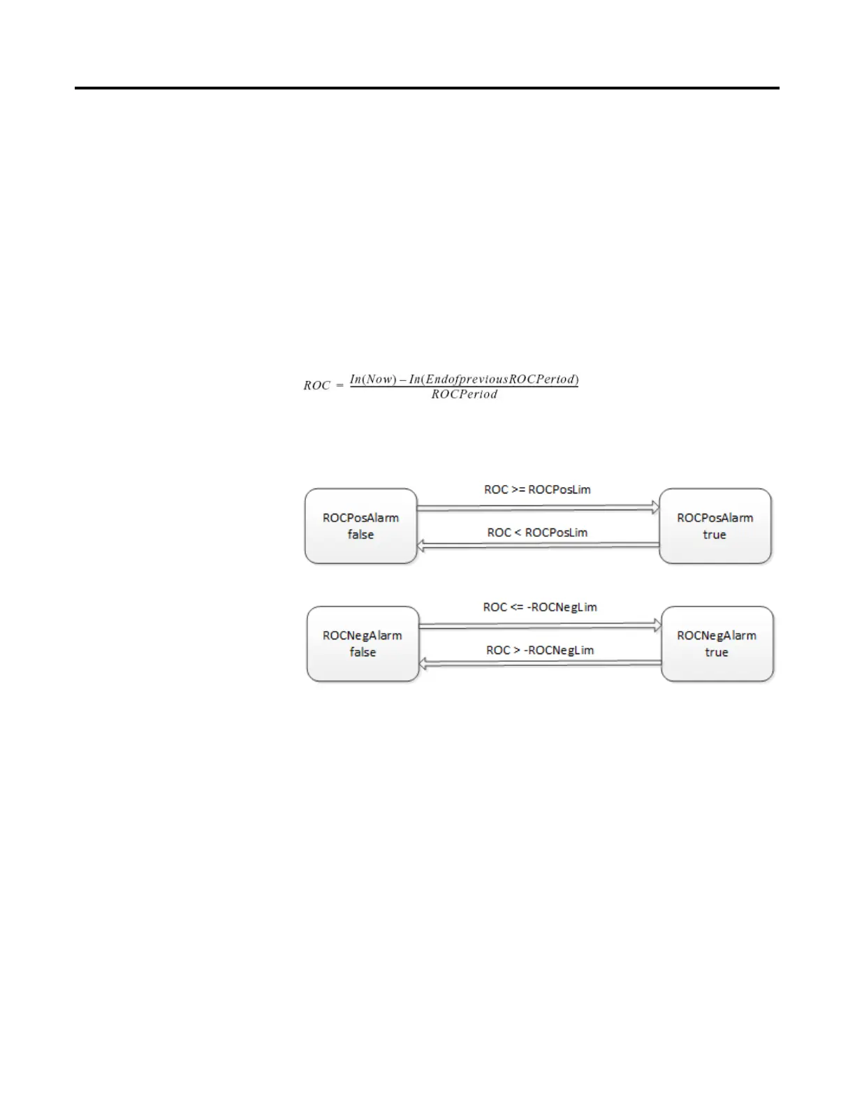
The ROC alarm calculates the rate-of-change as:
The instruction performs this calculation when the ROCPeriod expires. Once the
instruction calculates the ROC, it determines alarms as:
Monitoring the ALM Instruction
There is an operator faceplate available for the ALM instruction.
Affects Math Status Flags
No
Major/Minor Faults
None specific to this instruction. See Common Attributes for operand-related
faults.
 Loading...

