Equipment Phase Instructions
454 Rockwell Automation Publication 1756-RM006K-EN-P - November 2018
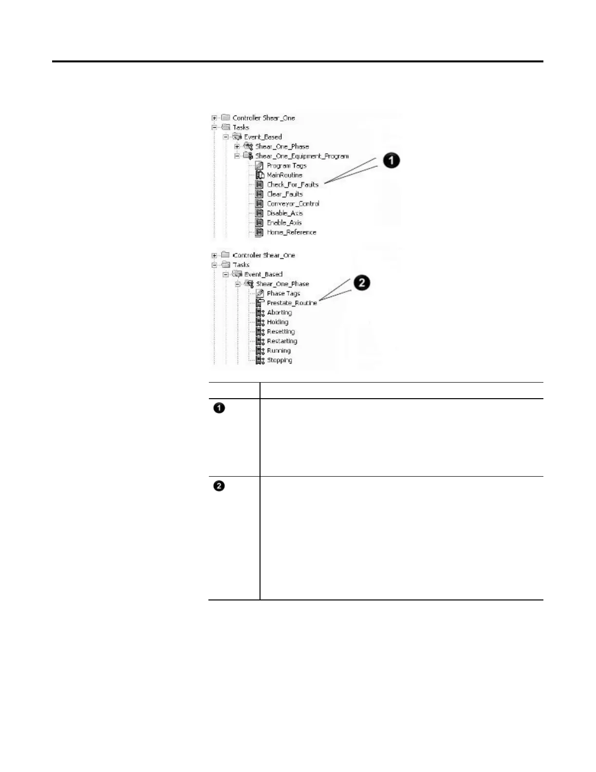
Example
Number Description
The equipment program watches for the these faults:
• Faulted axis
• Jammed material
If there is a fault, then
Local_Interface.Equipment_Faults_Cleared = 0. This tag is an alias for the controller-scoped
tag Shear_1.
The prestate routine of the equipment phase watches for the equipment program to signal a fault.
• If Interface_To_Equipment.Equipment_Faults_Cleared=0 then there is a fault.
• Both Interface_To_Equipment and Local_Interface as aliases for Shear_1, so they have the same
values.
If there is a fault, then
Give the Shear_One_Phase equipment phase the abort command. The POVR instruction makes sure
the command works, even if someone has manual control of the equipment phase through Logix
Designer software.
The PFL instruction sets the failure code for Shear_One_Phase = 333.
The Fault_Strobe keeps these actions to a single scan.
 Loading...

