16
Installation Considerations
For further information visit: www.abpowerflex.com or www.ab.com/support/abdrives
Power Wiring
PowerFlex 400 drives have the following built in protective features to help simplify installation.
• Ground fault protection while starting and running ensures reliable operation
• Electronic motor overload protection increases motor life
• 6kV transient protection provides increased robustness for 380-480V system voltages
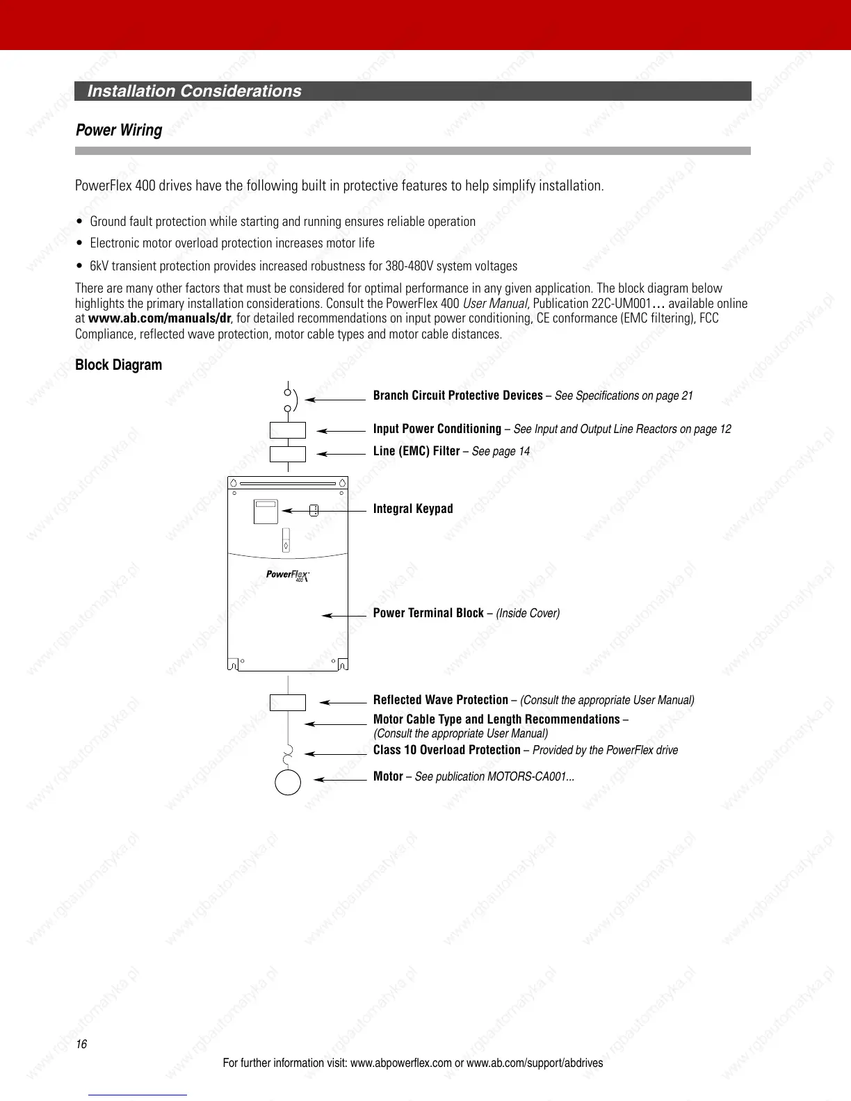
There are many other factors that must be considered for optimal performance in any given application. The block diagram below
highlights the primary installation considerations. Consult the PowerFlex 400 User Manual, Publication 22C-UM001
… available online
at www.ab.com/manuals/dr, for detailed recommendations on input power conditioning, CE conformance (EMC filtering), FCC
Compliance, reflected wave protection, motor cable types and motor cable distances.
Block Diagram
Branch Circuit Protective Devices – See Specifications on page 21
Class 10 Overload Protection – Provided by the PowerFlex drive
Line (EMC) Filter – See page 14
Motor – See publication MOTORS-CA001...
Motor Cable Type and Length Recommendations –
(Consult the appropriate User Manual)
Integral Keypad
Input Power Conditioning – See Input and Output Line Reactors on page 12
Reflected Wave Protection – (Consult the appropriate User Manual)
Power Terminal Block – (Inside Cover)

 Loading...


