3
Product Overview
For further information visit: www.abpowerflex.com or www.ab.com/support/abdrives
Packaging
• IP20, NEMA/UL Type 1 - For conventional mounting inside or
outside a control cabinet in a 45°C (113°F) ambient.
• Flange Type - Frame C ratings through 15 kW (20 HP) @ 380-
480V AC and 7.5 kW (10 HP) @ 200-240V AC allow for mounting
heatsink through back of an enclosure, thus removing a large
portion of the heat inside a cabinet. The backside is rated IP66,
NEMA/UL Type 4X/12 for both indoor and outdoor use.
• Installation flexibility is enhanced by the UL Plenum rating
allowing for direct mounting in an air handling system.
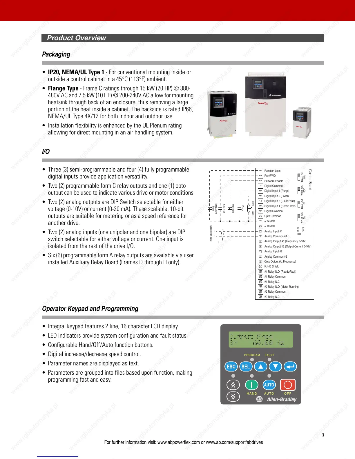
I/O
• Three (3) semi-programmable and four (4) fully programmable
digital inputs provide application versatility.
• Two (2) programmable form C relay outputs and one (1) opto
output can be used to indicate various drive or motor conditions.
• Two (2) analog outputs are DIP Switch selectable for either
voltage (0-10V) or current (0-20 mA). These scalable, 10-bit
outputs are suitable for metering or as a speed reference for
another drive.
• Two (2) analog inputs (one unipolar and one bipolar) are DIP
switch selectable for either voltage or current. One input is
isolated from the rest of the drive I/O.
• Six (6) programmable form A relay outputs are available via user
installed Auxiliary Relay Board (Frames D through H only).
Operator Keypad and Programming
• Integral keypad features 2 line, 16 character LCD display.
• LED indicators provide system configuration and fault status.
• Configurable Hand/Off/Auto function buttons.
• Digital increase/decrease speed control.
• Parameter names are displayed as text.
• Parameters are grouped into files based upon function, making
programming fast and easy.
Function Loss
Run/FWD
Software Enable
Digital Common
Digital Input 1 (Purge)
Digital Input 2 (Local)
Digital Input 3 (Clear Fault)
Digital Input 4 (Comm Port)
Digital Common
Opto Common
+ 24VDC
+ 10VDC
Analog Input #1
Analog Common #1
Analog Output #1 (Frequency 0-10V)
Analog Output #2 (Output Current 0-10V)
Analog Input #2
Analog Common #2
Opto Output (At Frequency)
RJ-45 Shield
#1 Relay N.O. (Ready/Fault)
#1 Relay Common
#1 Relay N.C.
#2 Relay N.O. (Motor Running)
#2 Relay Common
#2 Relay N.C.
1 2 3 4 5 6 7 8 9 10 11 12 13 14 15 16 17 18 19 20 R1 R2 R3 R4 R5 R6
AO1
10V 20MA
AO2
10V 20MA
AI1
10V 20MA
AI2
10V 20MA
SNK
SRC
Control Board
Hand Auto
Purge
Interlocks
Auto Start
Freeze/Fire
Stats
+ –
Speed Ref. Input

 Loading...


