17
Installation Considerations
For further information visit: www.abpowerflex.com or www.ab.com/support/abdrives
Power Terminal Block
Terminal Block Specifications
➊ Maximum/minimum sizes that the terminal block will accept - these are not recommendations. If national or local codes require sizes outside this range, lugs may be
used.
Name Frame Description Wire Size Range ➊ Recommended
Torque
Maximum Minimum
Power Terminal Block C All power terminals 8.4 mm
2
(8 AWG) 1.3 mm
2
(16 AWG) 3.7 N-m (33 lb.-in.)
D All power terminals 33.6 mm
2
(2 AWG) 8.4 mm
2
(8 AWG) 5.1 N-m (45 lb.-in.)
E480V
37-45 kW
(50-60 HP)
All power terminals 33.6 mm
2
(2 AWG) 3.5 mm
2
(12 AWG) 5.6 N-m (49.5 lb.-in.)
E240V
30-37 kW
(40-50 HP)
480V
55-75 kW
(75-100 HP)
All power terminals 107.2 mm
2
(4/0 AWG) 53.5 mm
2
(1/0 AWG) 19.5 N-m (173 lb.-in.)
F All power terminals 152.5 mm
2
(300 MCM) 85.0 mm
2
(3/0 AWG) 19.5 N-m (173 lb.-in.)
G All power terminals 152.5 mm
2
(300 MCM) 85.0 mm
2
(3/0 AWG) 29.4 N-m (260 lb.-in.)
H All power terminals 253.0 mm
2
(500 MCM) 127.0 mm
2
(250 MCM) 40.0 N-m (354 lb.-in.)
I/O Terminal Block All Signal and control connections 1.3 mm
2
(16 AWG) 0.13 mm
2
(26 AWG) 0.5-0.8 N-m (4.4-7 lb.-in.)
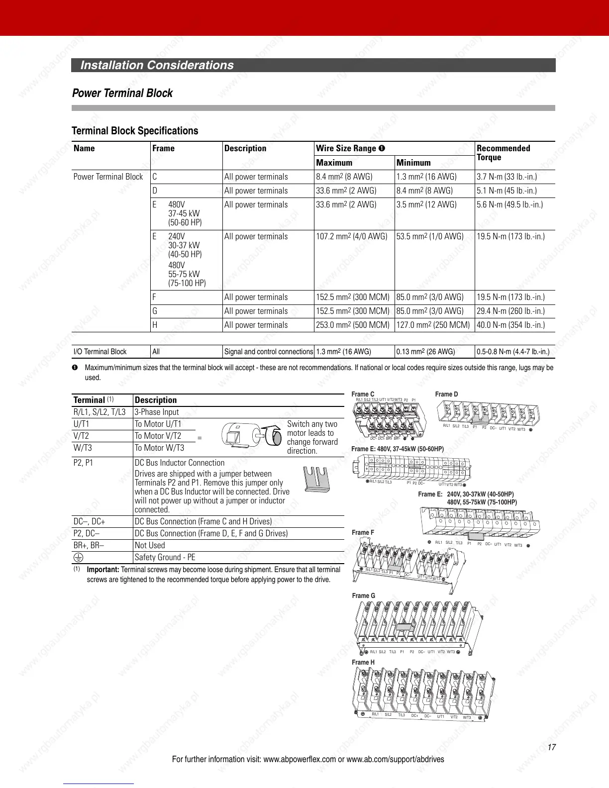
Terminal
(1)
Description
R/L1, S/L2, T/L3 3-Phase Input
U/T1 To Motor U/T1
=
Switch any two
motor leads to
change forward
direction.
V/T2 To Motor V/T2
W/T3 To Motor W/T3
P2, P1 DC Bus Inductor Connection
Drives are shipped with a jumper between
Terminals P2 and P1. Remove this jumper only
when a DC Bus Inductor will be connected. Drive
will not power up without a jumper or inductor
connected.
DC–, DC+ DC Bus Connection (Frame C and H Drives)
P2, DC– DC Bus Connection (Frame D, E, F and G Drives)
BR+, BR– Not Used
Safety Ground - PE
(1)
Important: Terminal screws may become loose during shipment. Ensure that all terminal
screws are tightened to the recommended torque before applying power to the drive.
Frame C
Frame D
R/L1
S/L2
T/L3
P1
P2
DC–
U/T1
V/T2
W/T3
R/L1 S/L2 T/L3
U/T1 V/T2
W/T3
P2 P1
BR–BR+DC+DC–
Frame E: 480V, 37-45kW (50-60HP)
R/L1
S/L2
T/L3
P1
P2
DC–
U/T1
V/T2
W/T3
R/L1
S/L2
T/L3
P1
P2
DC–
U/T1
V/T2
W/T3
Frame F
R/L1
S/L2
T/L3
P1
P2
DC–
U/T1
V/T2
W/T3
Frame E: 240V, 30-37kW (40-50HP)
480V, 55-75kW (75-100HP)
Frame G
Frame H
R/L1
S/L2
T/L3
P1
P2
DC–
U/T1
V/T2
W/T3
R/L1
S/L2
T/L3
DC–
DC+
U/T1
V/T2
W/T3

 Loading...


