18
Installation Considerations
For further information visit: www.abpowerflex.com or www.ab.com/support/abdrives
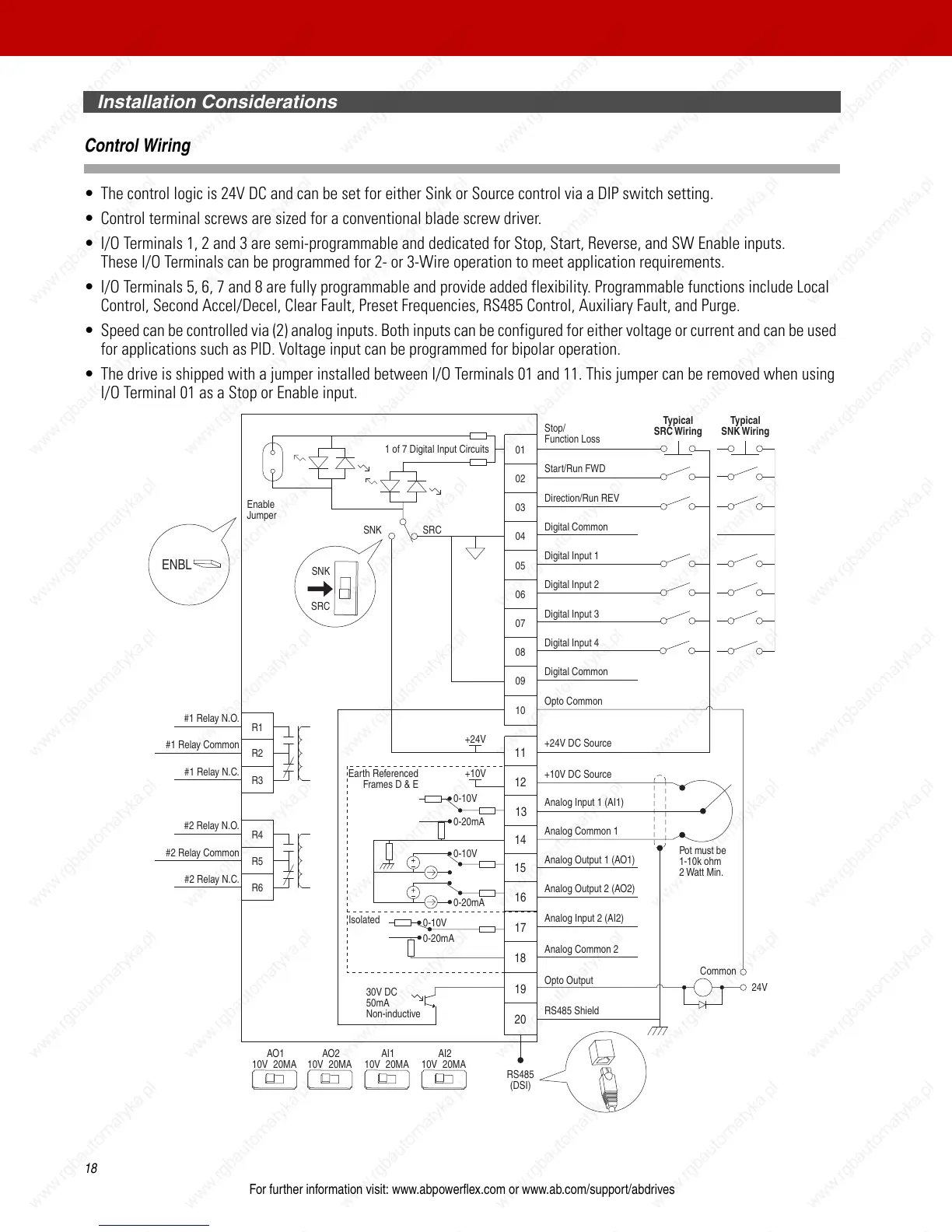
Control Wiring
• The control logic is 24V DC and can be set for either Sink or Source control via a DIP switch setting.
• Control terminal screws are sized for a conventional blade screw driver.
• I/O Terminals 1, 2 and 3 are semi-programmable and dedicated for Stop, Start, Reverse, and SW Enable inputs.
These I/O Terminals can be programmed for 2- or 3-Wire operation to meet application requirements.
• I/O Terminals 5, 6, 7 and 8 are fully programmable and provide added flexibility. Programmable functions include Local
Control, Second Accel/Decel, Clear Fault, Preset Frequencies, RS485 Control, Auxiliary Fault, and Purge.
• Speed can be controlled via (2) analog inputs. Both inputs can be configured for either voltage or current and can be used
for applications such as PID. Voltage input can be programmed for bipolar operation.
• The drive is shipped with a jumper installed between I/O Terminals 01 and 11. This jumper can be removed when using
I/O Terminal 01 as a Stop or Enable input.
04
05
06
07
01
02
03
08
09
10
12
13
14
15
16
17
18
19
20
11
Digital Common
Digital Common
Digital Input 1
Digital Input 2
Digital Input 3
Stop/
Function Loss
Start/Run FWD
Direction/Run REV
Digital Input 4
Opto Common
R1
R2
R3
#1 Relay N.O.
#1 Relay Common
#1 Relay N.C.
+24V DC Source
+10V DC Source
Analog Input 1 (AI1)
Analog Common 1
Analog Output 2 (AO2)
Analog Output 1 (AO1)
Analog Input 2 (AI2)
Analog Common 2
Opto Output
RS485 Shield
+24V
+10V
R4
R5
R6
#2 Relay N.O.
#2 Relay Common
#2 Relay N.C.
Typical
SNK Wiring
Typical
SRC Wiring
RS485
(DSI)
Enable
Jumper
30V DC
50mA
Non-inductive
Common
24V
ENBL
Pot must be
1-10k ohm
2 Watt Min.
SRCSNK
SNK
SRC
Earth Referenced
Frames D & E
0-10V
0-20mA
0-10V
0-20mA
0-10V
0-20mA
1 of 7 Digital Input Circuits
10V
20MA
AO1
10V
20MA
AO2
10V
20MA
AI1
10V
20MA
AI2
Isolated

 Loading...


