19
Installation Considerations
For further information visit: www.abpowerflex.com or www.ab.com/support/abdrives
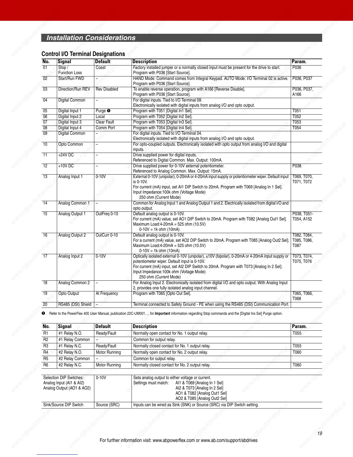
Control I/O Terminal Designations
➊ Refer to the PowerFlex 400 User Manual, publication 22C-UM001…, for Important information regarding Stop commands and the [Digital Inx Sel] Purge option.
No. Signal Default Description Param.
01 Stop /
Function Loss
Coast Factory installed jumper or a normally closed input must be present for the drive to start.
Program with P036 [Start Source].
P036
02 Start/Run FWD – HAND Mode: Command comes from Integral Keypad. AUTO Mode: I/O Terminal 02 is active.
Program with P036 [Start Source].
P036, P037
03 Direction/Run REV Rev Disabled To enable reverse operation, program with A166 [Reverse Disable].
Program with P036 [Start Source].
P036, P037,
A166
04 Digital Common – For digital inputs. Tied to I/O Terminal 09.
Electronically isolated with digital inputs from analog I/O and opto output.
05 Digital Input 1 Purge ➊ Program with T051 [Digital In1 Sel]. T051
06 Digital Input 2 Local Program with T052 [Digital In2 Sel]. T052
07 Digital Input 3 Clear Fault Program with T053 [Digital In3 Sel]. T053
08 Digital Input 4 Comm Port Program with T054 [Digital In4 Sel]. T054
09 Digital Common – For digital inputs. Tied to I/O Terminal 04.
Electronically isolated with digital inputs from analog I/O and opto output.
10 Opto Common – For opto-coupled outputs. Electronically isolated with opto output from analog I/O and digital
inputs.
11 +24V DC – Drive supplied power for digital inputs.
Referenced to Digital Common. Max. Output: 100mA.
12 +10V DC – Drive supplied power for 0-10V external potentiometer.
Referenced to Analog Common. Max. Output: 15mA.
P038
13 Analog Input 1 0-10V External 0-10V (unipolar), 0-20mA or 4-20mA input supply or potentiometer wiper. Default input
is 0-10V.
For current (mA) input, set AI1 DIP Switch to 20mA. Program with T069 [Analog In 1 Sel].
Input Impedance:100k ohm (Voltage Mode)
250 ohm (Current Mode)
T069, T070,
T071, T072
14 Analog Common 1 – Common for Analog Input 1 and Analog Output 1 and 2. Electrically isolated from digital I/O and
opto output.
15 Analog Output 1 OutFreq 0-10 Default analog output is 0-10V.
For current (mA) value, set AO1 DIP Switch to 20mA. Program with T082 [Analog Out1 Sel].
Maximum Load:4-20mA = 525 ohm (10.5V)
0-10V = 1k ohm (10mA)
P038, T051-
T054, A152
16 Analog Output 2 OutCurr 0-10 Default analog output is 0-10V.
For a current (mA) value, set AO2 DIP Switch to 20mA. Program with T085 [Analog Out2 Sel].
Maximum Load:4-20mA = 525 ohm (10.5V)
0-10V = 1k ohm (10mA)
T082, T084,
T085, T086,
T087
17 Analog Input 2 0-10V Optically isolated external 0-10V (unipolar), ±10V (bipolar), 0-20mA or 4-20mA input supply or
potentiometer wiper. Default input is 0-10V.
For current (mA) input, set AI2 DIP Switch to 20mA. Program with T073 [Analog In 2 Sel].
Input Impedance:100k ohm (Voltage Mode)
250 ohm (Current Mode)
T073, T074,
T075, T076
18 Analog Common 2 – For Analog Input 2. Electronically isolated from digital I/O and opto output. With Analog Input
2, provides one fully isolated analog input channel.
19 Opto Output At Frequency Program with T065 [Opto Out Sel]. T065, T066,
T068
20 RS485 (DSI) Shield – Terminal connected to Safety Ground - PE when using the RS485 (DSI) Communication Port.
No. Signal Default Description Param.
R1 #1 Relay N.O. Ready/Fault Normally open contact for No. 1 output relay. T055
R2 #1 Relay Common – Common for output relay.
R3 #1 Relay N.C. Ready/Fault Normally closed contact for No. 1 output relay. T055
R4 #2 Relay N.O. Motor Running Normally open contact for No. 2 output relay. T060
R5 #2 Relay Common – Common for output relay.
R6 #2 Relay N.C. Motor Running Normally closed contact for No. 2 output relay. T060
Selection DIP Switches:
Analog Input (AI1 & AI2)
Analog Output (AO1 & AO2)
0-10V Sets analog output to either voltage or current.
Settings must match: AI1 & T069 [Analog In 1 Sel]
AI2 & T073 [Analog In 2 Sel]
AO1 & T082 [Analog Out1 Sel]
AO2 & T085 [Analog Out2 Sel]
Sink/Source DIP Switch Source (SRC) Inputs can be wired as Sink (SNK) or Source (SRC) via DIP Switch setting.

 Loading...


