160 Rockwell Automation Publication MOTION-UM003K-EN-P - January 2019
Chapter 8 Configuration Examples for a Kinetix Drive
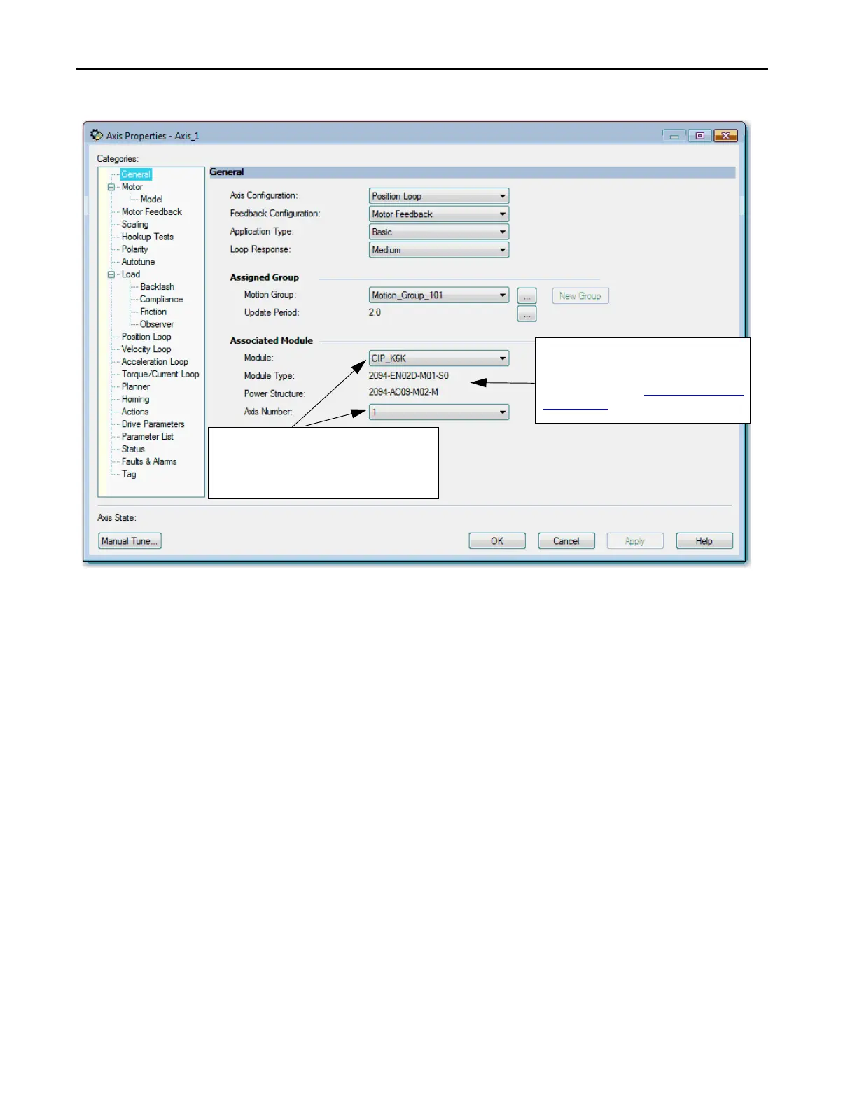
Figure 24 - Example 1: General Dialog Box, Position Loop with Motor Feedback Only
When you select the Position Loop with Motor Feedback, the Motor
and Motor Feedback dialog boxes become available.
4. Choose Catalog Number as the Motor Data Source.
The newly created Kinetix 6500 drive module name is
the default. The Axis Number defaults to 1, indicating
the primary axis of the drive. Axis Number 2 is used only
for configuring a Feedback Only axis.
The type of drive you selected and the power
structure you assigned via the Kinetix 6500 Module
Properties.
For more information, see Add a Kinetix EtherNet/IP
Drive on page 32.
TIP After you have configured the axis and you change the Axis Configuration
type or the Axis Number, some of the configuration information is set to
default values. This change can cause some previously entered data to be
reset back to its default setting.

 Loading...


