70 Rockwell Automation Publication MOTION-UM003K-EN-P - January 2019
Chapter 4 Configure Integrated Motion Control Using Kinetix 5700 Drives
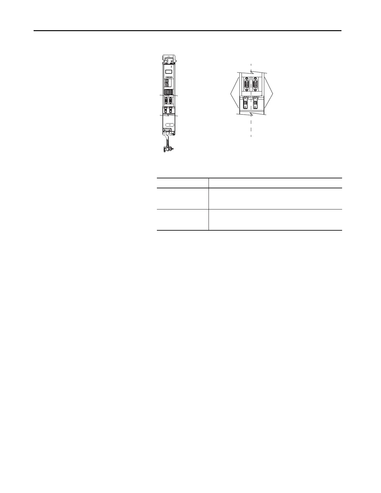
Figure 7 - Dual-axis Inverter Feedback
The Feedback Devices are configured for either the DSL Feedback Port
or the Universal Feedback Port.
3. From the Axis x pull-down menu, choose an axis to assign to that motor
feedback or auxiliary feedback device.
4. From the Feedback Device pull-down menu, choose either DSL
Feedback x Port or Universal Feedback x Port to associate with each
axis.
5. Click New Axis.
1
I/O-A
6
10
1
I/O-B
6
5
10
UFB-A
UFB-B
D+
D-
D+
D-
MF-A
MF-B
2
1
5
MOD–
NET–
UFB-A
UFB-B
D+
D-
D+
D-
MF-A
MF-B
Kinetix 5700
Dual-axis Inverter
Universal and DSL Hiperface
Feedback Connectors
See Detail A
Motion Safety 1
Associated Axes - Axis 1
Detail A
Motion Safety 2
Associated Axes - Axis 3
UFB-B
MF-B
UFB-A
MF-A
Motor Feedback Options Description
DSL Feedback Port
Applies to motors and actuators compatible with the 2198-KITCON-DSL
connector kit and 2198-H2DCK converter kit (series B or later). These kits
plug into the 2-pin motor feedback (MF) connector.
Universal Feedback Port
Applies to motors and actuators compatible with the 2198-K57CK-D15M
universal connector kit. These kits plug into the 15-pin universal feedback
(UFB) connector.

 Loading...


