Rockwell Automation Publication MOTION-UM003K-EN-P - January 2019 89
Configure Integrated Motion Control Using Kinetix 5700 Drives Chapter 4
Table 2 6 compares the feedback configuration types for the Kinetix
drives.
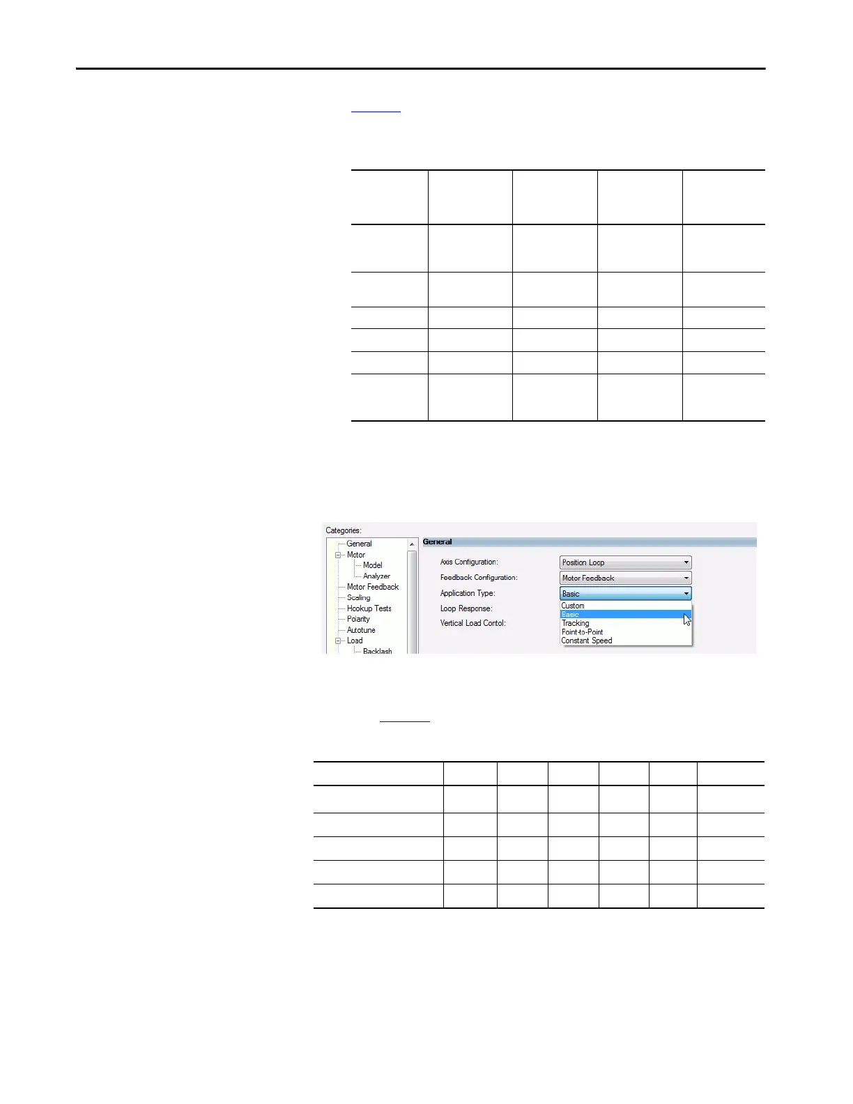
4. Choose an Application Type, if applicable.
The Application Type determines the type of motion control
application. This attribute is used to set the Gain Tuning Configuration
Bits. Tab le 27
illustrates the gains established based on application type.
Table 26 - Compare the Feedback Configuration Types for the Drives
Feedback
Type
Kinetix 5700
Dual-axis
Inverter Type
Kinetix 5700
Single-axis
Inverter Type
Kinetix 5700
DC Bus Power
Supply
Kinetix 5700
Regenerative
Bus Supply
Motor Feedback Position Loop (P),
Velocity Loop (V),
Torque Loop (T)
Position Loop (P),
Velocity Loop(V),
Torque Loop (T)
— —
Load Feedback Position Loop (P),
Velocity Loop (V)
Position Loop (P),
Velocity Loop(V)
— —
Dual Feedback Position Loop (P) Position Loop (P)
— —
Dual Integrator — — — —
Master Feedback Feedback Only (E) Feedback Only (E) — —
No Feedback
Frequency Control
(F)
Frequency Control
(F)
Non-regenerative
AC/DC Converter
(N)
Regenerative
AC/DC Converter
(G)
TIP The following General Options are available in an inverter configuration.
Table 27 - Customize Gains to Tune
Application Type Kpi Kvi ihold Kvff Kaff torqLPF
Custom
(1)
(1) If you set the type to Custom, you can control the individual gain calculations by changing the bit settings in the Gain Tuning
Configuration Bits Attribute.
——————
Basic No No No Yes No Yes
Tracking No Yes No Yes Yes Yes
Po in t- to -Po in t Ye s No Yes No N o Ye s
Constant Speed No Yes No Yes No Yes

 Loading...


