343-3512A (03/13)
13 of 27
Optimize
IMPORTANT
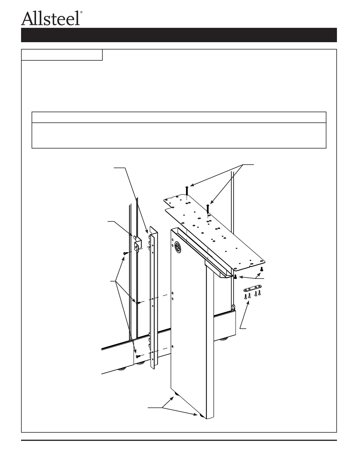
The primary uses of support legs are at 90° panel junctions and/or to support adjoining worksurfaces.
When used to support a single worksurface, the worksurface grommet hole will be partially blocked.
If full access of grommet hole is required, replace support leg with a cantilever support bracket.
Illustration 2: Support Leg
Step 1 - Insert panel attachment
bracket tabs into panel
slots and lift bracket,
hooking tabs behind panel
frame.
Step 2 - Insert anti-dislodgement
bracket into panel slot
and align bottom hole of
bracket with top hole of
full end panel support.
Step 3 - Install sheet metal screws
through top holes of each
pair of panel attachment
bracket holes and into top
holes of support leg.
Note: Insert color matched
hole plugs into holes
on opposite side of
support leg.
Assembly:
1. Assemble support leg, panel attachment bracket, and at bracket in a conguration where the leg is under the
largest worksurface.
2. Right-hand conguration is shown. Attach panel attachment bracket to opposite side of support leg for a left-hand
conguration. Flip at bracket over for left-hand applications.
Step 6 - Install wood
screws through
round holes in
at bracket and
into bottom of
worksurface.
Step 5 - Install two at head
sheet metal screws
through larger holes
in at bracket and
into top of support
leg.
Note: Right-hand
application shown.
Flip bracket over for
left-hand application.
Step 7 - Connect tie plate
between two
worksurfaces. Install
wood screws through
holes in tie plate and
into worksurfaces.
Step 4 - Turn leveling glides
until glides are at
against oor.
Worksurface Supports Installation