343-3512A (03/13)
2 of 27
Optimize
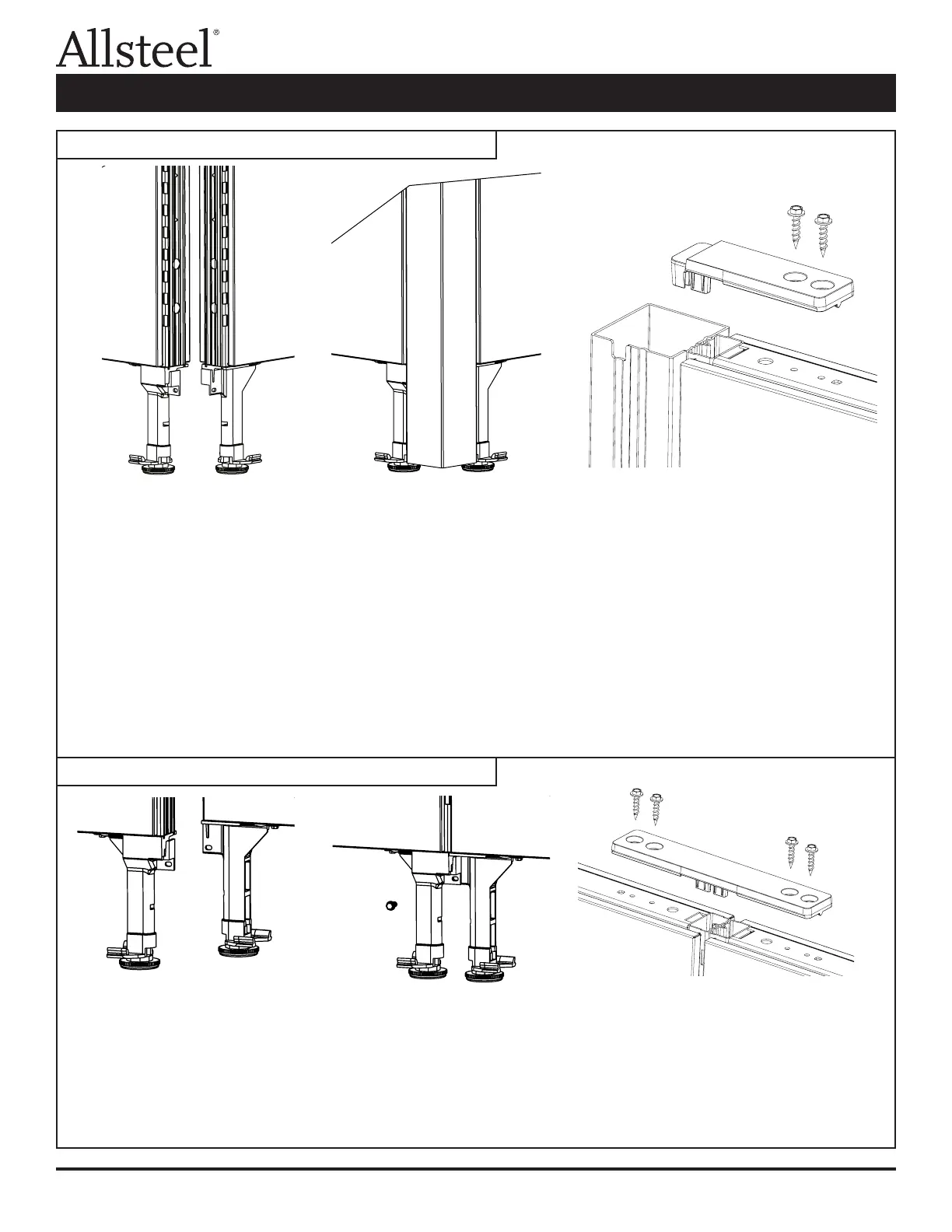
1. Align the panels into the conguration required. Locate notches in bottom of corner connector to the glide tower.
2. Lift the corner connector post and slide the notches onto the tab of each glide tower.
3. Secure the corner connector post to the panel by pressing the hub of the bracket into the corner connector
post and slotted steel panel tube. Do not insert screws into connector brackets until all panels required for the
connection are in place.
4. Level panels as they are assembled.
5. Repeat for other panel connections ("T, "S", or "X").
6. Attach the brackets to the panels using the screws (Fastener #2) provided, do not over torque, and do not
cut fabric.
NOTE: If a connection must be lifted after the screws are installed on a panel run longer than six feet, unscrew the
panel connector brackets prior to lifting the panels.
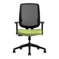
1. Remove the kickplate from one side of each panel.
2. Position panels together with the slotted vertical tubes in alignment.
3. Attach the panels by inserting a screw (F4) through the slot in the glide tower into the glide tower of the
adjacent panel.
4. Secure the panels at the top by installing black inline connector strap into slotted steel tubes of both panels.
5. Attach the connector to the panels using four screws (F2) provided. Do not over torque.
6. Reinstall kickplates.
Illustration 1: Panel to Corner Connector
Illustration 2: Panel to Panel Connector
Panel Connections and Trim Installation