343-3512A (03/13)
3 of 27
Optimize
Panel to Corner Connector Post:
1. Attach the bottom of the corner connector post to the glide tower
tab on the panel.
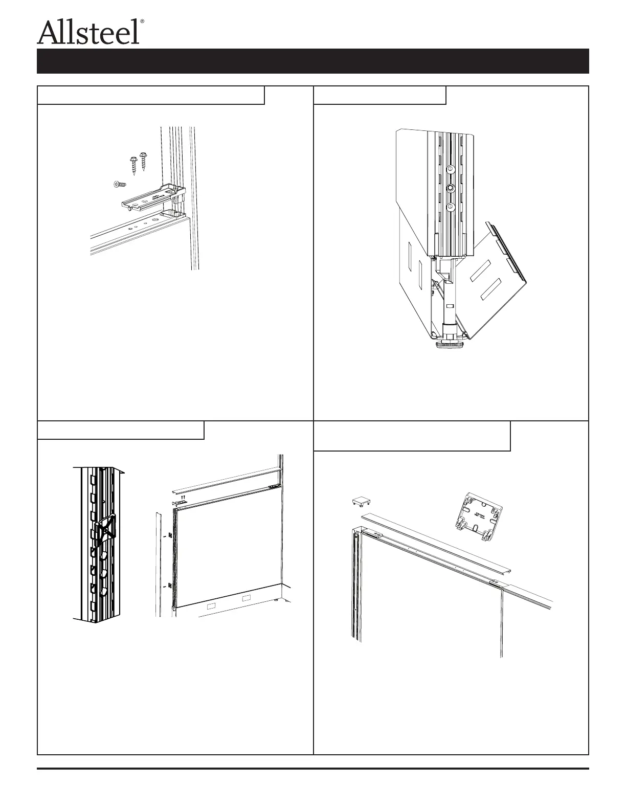
2. Attach VH bracket to the panel by inserting the tabs into the vertical
tube and securing with two (F2) screws.
3. Center the bracket on the corner post and insert the self drilling
screw (F5) into the vertical groove of the corner connector.
Panel to Panel:
1. Attach the bottom of the panels with (F4) screw. (See panel to
panel connector.)
2. Attach to VH bracket to the panel by inserting the tabs into the
vertical tube and securing with two (F2) screws.
3. Center the bracket on the slotted vertical and insert the self drilling
screw (F5) into the 0.150 diameter hole of the panel tube.
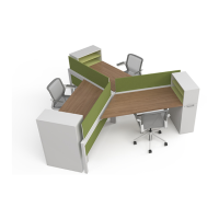
1. Install the plastic end trim clips into the slotted steel tube with the
screws (F3) provided. The rib of the clip locates into the groove of
the tube and it is attached into the 0.150 holes.
2. Snap the end trim extrusion over the clips.
3. Insert the top trim bracket into the end trim extrusion.
4. Attach the top trim bracket to the panel using the two screws
(F2) provided.
5. The top cap snap ts over the attachment connectors.
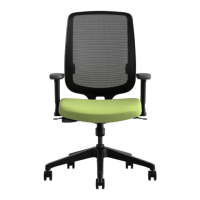
To remove: Pull kickplate from top edge by panel and unhinge from
glide towers.
To install: Place kickplate slots over glide tower tabs. Press on top of
kickplate near glide towers to snap into place against panel.
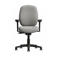
1. Using pliers, break out the appropriate windows (if necessary) on
the corner connector top cap. File rough edges if necessary.
2. Press cap into top of connector post placing the open windows over
the attachment connectors.
Illustration 3: Variable Height Connections Illustration 4: Kickplate
Illustration 5: End of Run Trim
Illustration 6: Trim for "T", "L", "S", or
"X" Intersections
Panel Connections and Trim Installation