343-3512A (03/13)
4 of 27
Optimize
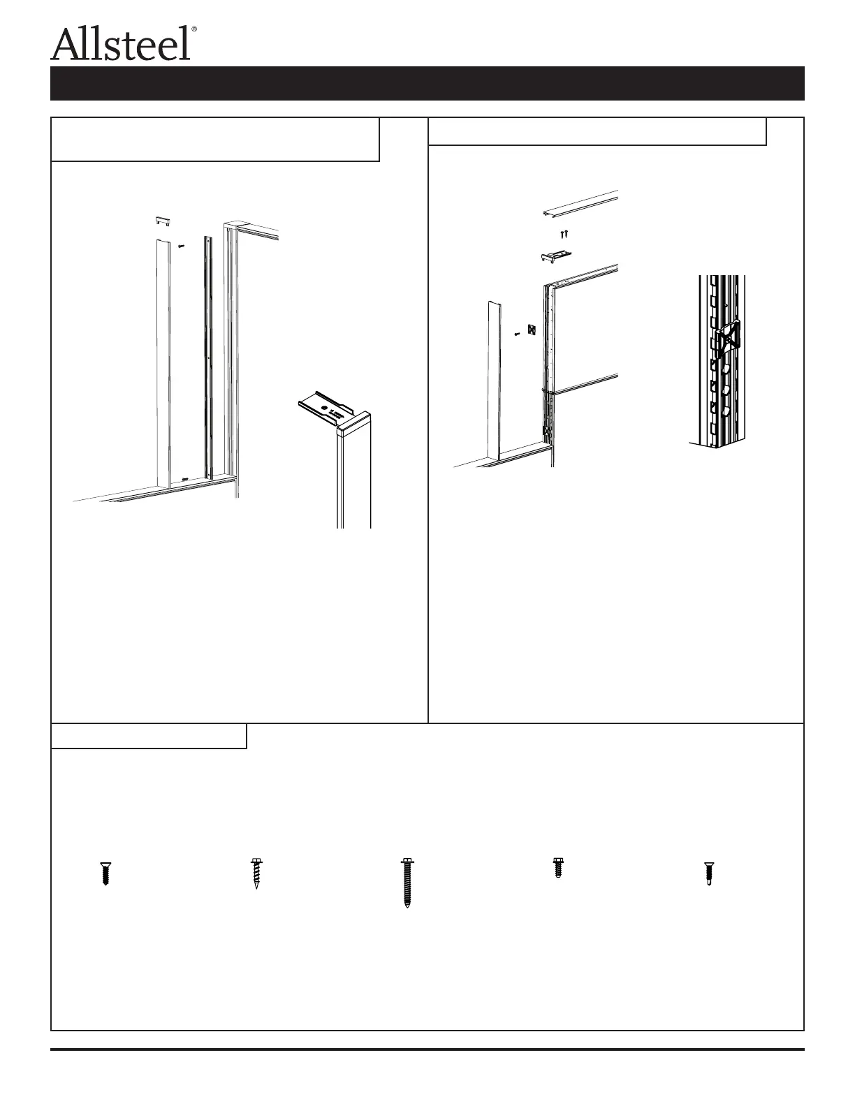
1. Install the top cap on the lower panel.
2. Mount the variable height plastic extrusion to the
corner connector post using the alignment grooves
and self-drilling screws (F5) provided.
3. Press the top trim bracket into the decorative
extrusion; break off the bracket portion.
4. Snap the decorative extrusion over the plastic
extrusion.
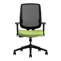
1. Install the top cap on the lower panel.
2. Install the plastic end trim clips into the slotted steel
tube with the screws (F3) provided. The rib of the clip
locates into the groove of the tube and it is attached
into the 0.150 holes.
3. Snap the decorative extrusion over the clips.
4. Insert the top trim bracket into the end decorative
extrusion.
5. Attach the top trim bracket to the panel using two
screws (F2) provided.
6. The top cap snap ts over the attachment connectors.
Illustration 7: Variable Height Panel to Corner
Connector Trim
Illustration 8: Inline Variable Height Panel Trim
Illustration 9: Hardware
F1 F2 F3 F4 F5
#10 – 16 x 3/4 #8 – 18 x 3/4 #12 – 14 x 1 1/2 #10 – 16 x 1/2 #10 – 8 x 3/4
Phillips Head Hex Head Hex Head Hex Head Phillips Head
Self Drilling
Panel Connections and Trim Installation