343-3512A (03/13)
5 of 27
Optimize
Stacking Panel
Warning
• Add no more than one stacking panel to any base panel.
• A severe impact or drop may cause immediate breakage or enough damage so that a glazed panel breaks
later for no apparent reason.
Conguration Restrictions
• Structural stacking panel congurations must have adjacent panels or corner connectors of the same height
at each end of the run.
• Stacking panel congurations that create a variable height will require the use of a variable height nish kit
as listed in the pricer. Use of the variable height conguration is not allowed if the stacker is to be congured
with hanging accessories.
• Variable height congurations of more than 30" are not allowed.
1. Before installing stacking panel to base panel, base panel must not be attached to any other panel or corner
connector.
2. Remove top cap of base panel. On wider units, remove top cap center clip.
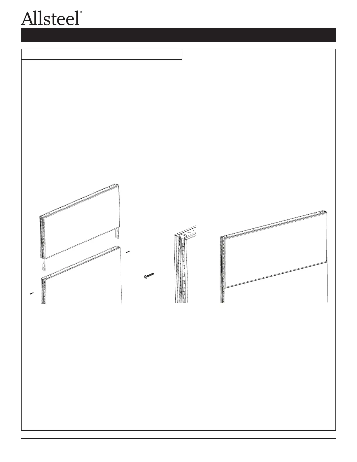
3. lnstall attachment legs of stacking panel into top slotted tube of base panel. Verify the stacker is fully seated
into the base panel.
4. Secure stacking panel to base panel on both sides using two screws (F3) provided.
5. Install the top cap onto the stacker when trimming out the panels.
Note: When attaching a connector or trim bracket to a glass stacker, use the screws provided in the stacker
hardware pack. If the 3/4" long standard panel screws (F2) are used, they could damage the stacker.
Illustration 1: Optimize Panel System Stacking Panel
Stacking Panel Assembly